Liquid crystal display device

a liquid crystal display and display device technology, applied in static indicating devices, instruments, non-linear optics, etc., can solve the problems of irregular alignment, narrow angular field of view provided thereby, and takes a time in the order of seconds to restore, so as to prevent flickering and reduce parasitic capacitance. non-uniform

Active Publication Date: 2005-12-22
HANNSTAR DISPLAY CORPORATION
View PDF10 Cites 24 Cited by
  • Summary
  • Abstract
  • Description
  • Claims
  • Application Information

AI Technical Summary

Benefits of technology

[0026] (3) Consequently, when a liquid crystal panel is depressed, re-aligning of the liquid-crystal molecules, is quickly settled. In addition,

Problems solved by technology

While enhancement of display quality is expected in such applications, the TN-TFT liquid crystal display device has a problem where an angular field of view provided thereby is narrow.
In Patent Literature 2, there arises a problem where, when a panel surface of a liquid crystal display device is depressed, a wavy alignment irregularity occurs in liquid crystal molecules, and it takes a time in th

Method used


Image

  • Liquid crystal display device
  • Liquid crystal display device
  • Liquid crystal display device

Examples


second embodiment

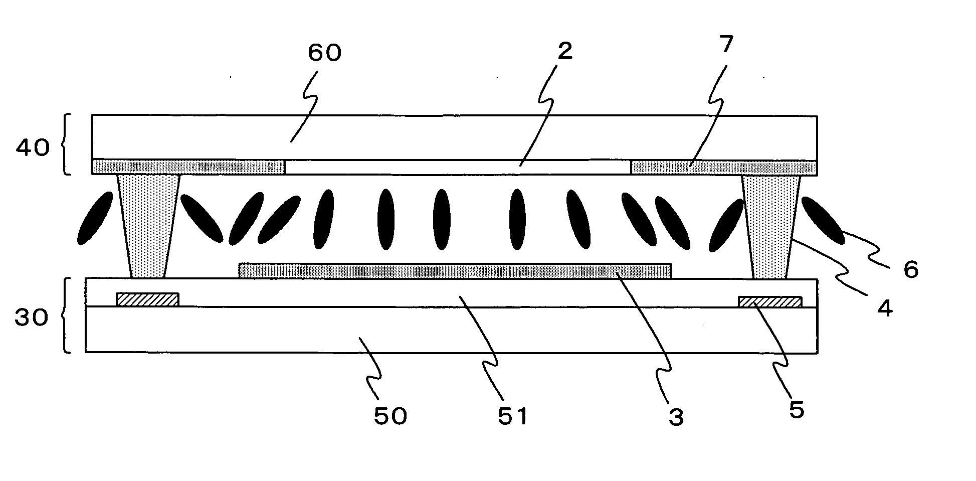
[0074] In the liquid crystal display device of the present invention, while the picture electrode is divided into the three sub-picture electrodes 3A along the signal line 5, it is also possible to divide the picture electrode along a scanning line, or to divide the picture electrode in the vertical and horizontal directions with both lines. The columnar spacer is disposed at a position where it is lapped over the scanning liner or the signal line.

[0075] Next, a liquid crystal display device in a third exemplary embodiment of the present invention is described. A basic configuration of the liquid crystal display device of the third embodiment is similar to that of the second embodiment. The third embodiment is different to the second embodiment in that, in the third embodiment, instead of providing a slit on a common electrode, a cross-shaped protruding structure is provided on a common electrode disposed at a position where the common electrode laps over a picture electrode, while ...

third embodiment

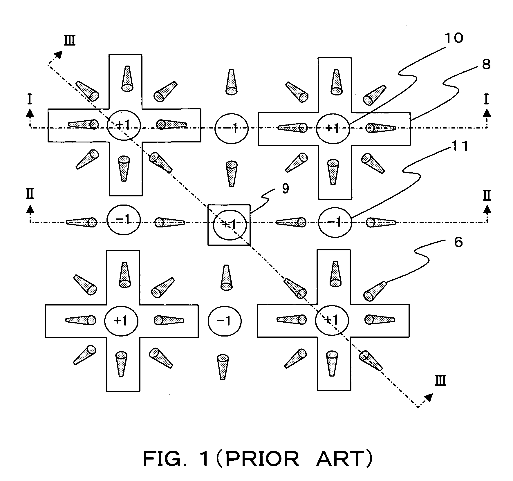
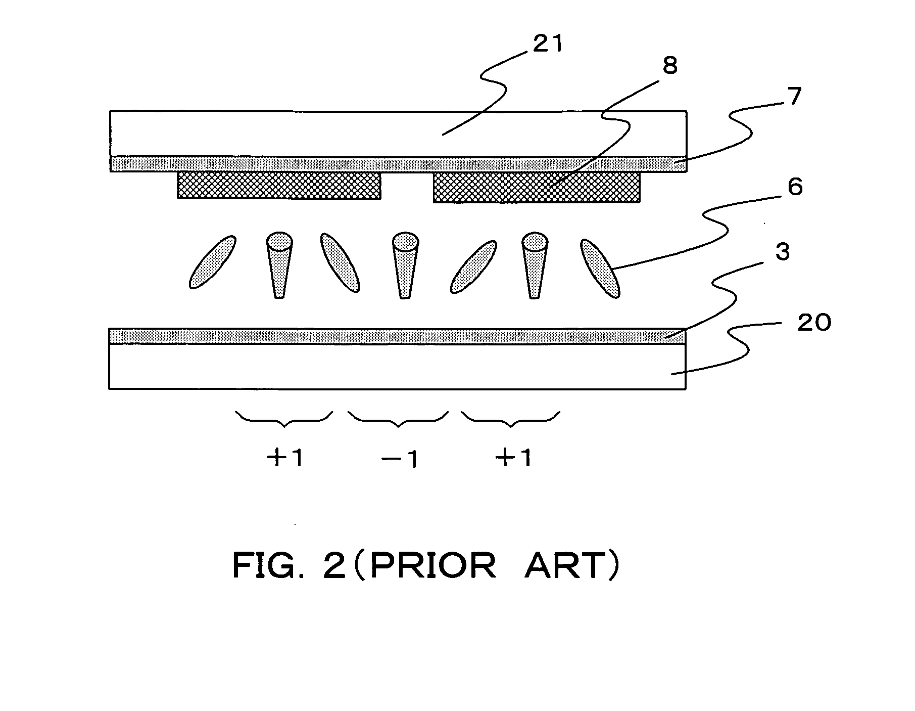
[0081] Because of the effect of the columnar spacer 4 and the quadrate protruding structure 8, the position of the singularity is determined as shown in FIG. 12. That is, a singular point 10A of +1 occurs in the vicinity of the columnar spacer 4, while a singular point 10C of +1 occurs on the quadrate protruding structure 8. Moreover, a singular point of −1 (not shown) occurs between the end of the picture electrode 3A and the end of the signal line 5. When pressing a panel surface with a finger, re-aligning of the alignment of the liquid crystal molecules occurs in a display area at the singular point of +1 as a base point of the singular point having occurred in the middle of the cross-shaped protruding structure 2A. On the signal line 5, re-aligning of the alignment of the liquid crystal molecules quickly occurs at the singularity of +1 as a base point of the singularity having occurred in the vicinity of the columnar spacer 4 and on the quadrate protruding structure 8. In this m...


PUM


Abstract

A picture electrode of an MVA liquid crystal display device has a configuration where sub-picture electrodes are successively provided, while a cross-shaped slit is provided as an alignment restriction member on a common electrode of the side of a counter substrate. A columnar spacer is provided on a signal line of a TFT substrate in conformity to a position of a singular point of an alignment of liquid crystal molecules, the singularity occurring in a display region. This structure makes it possible, when a panel surface is depressed, to cause quick re-aligning of the liquid crystal molecules at the singular point of +1, as a base point, which has occurred at a center of the cross-shaped slit and in the vicinity of the columnar spacer, hence achieving a speedy recovery of displaying.

Description

BACKGROUND OF THE INVENTION [0001] 1. Field of the Invention [0002] The present invention relates to a liquid crystal display device and particularly to a multi-domain vertical alignment liquid crystal display where a columnar spacer is provided on a wiring part. [0003] 2. Description of the Related Art [0004] A liquid crystal display device has various features of the thin type, lightness, and low power consumption, or the like. The liquid crystal display devices have been widely used as not only the display monitor for a personal computer, a word processor, office automation (OA) equipment, personal digital assistance (PDA), and an in-vehicle navigation but also a display device of the LCD TV, and the like. [0005] The display operation mode of a liquid crystal device, which is currently used most, is a normally white mode using a twisted nematic (TN) liquid crystal. [0006] The liquid crystal display includes electrodes which are respectively formed on the opposed faces of two shee...

Claims


Application Information

Patent Timeline
IPC IPC(8): G02F1/133G02F1/1333G02F1/1337G02F1/139
CPCG02F1/133707G02F1/1393G02F1/133753G02F1/1337
Inventor ISHII, TOSHIYA
Owner HANNSTAR DISPLAY CORPORATION
Why Eureka
Try Eureka