
Circuit arrangement for limitation of over-voltages in energy storage modules

a technology of energy storage modules and circuit arrangements, which is applied in the direction of secondary cell servicing/maintenance, process and machine control, instruments, etc., can solve the problems of affecting and achieve the effect of improving the overall efficiency of the energy storage modul

Inactive Publication Date: 2005-12-22
INVENTIO AG
View PDF3 Cites 12 Cited by
  • Summary
  • Abstract
  • Description
  • Claims
  • Application Information

AI Technical Summary

Benefits of technology

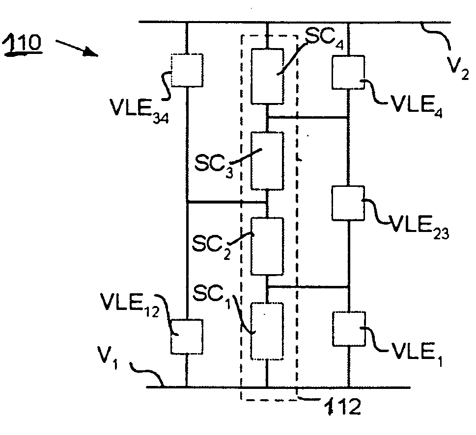
[0009] Accordingly, it is an object of the present invention to give an over-voltage protection for modules of energy storage elements which can be realized in simple and economic manner and which ensures reliable protection against damage of energy storage elements in the case of over-voltages.
[0010] It is another object of the present invention to give, in the case of use of super-capacitors in energy storage modules, a circuit arrangement which prevents damage of energy storage elements in the event of over-voltages due to tolerances in capacitance.
[0011] The present invention is based on the notion that Zener diodes offer an economic and easily connectible possibility for voltage limitation. Since energy storage elements usually have a low permissible voltage and consequently have to be used in a series circuit in order to be able to store a greater level of charge, the obvious approach would be to connect in parallel with each energy storage element, as is already known from the state of the art, a Zener diode with a small breakdown voltage corresponding with the maximum permissible voltage of the corresponding energy storage element. Since, however, the Zener diodes have for low voltages a gentle, relatively soft characteristic curve which already allows flow of a discharge current at voltages below the breakdown voltage this is disadvantageous for the overall efficiency of the energy storage module. The storage life of the overall module is reduced by the discharge current already flowing prior to the breakdown voltage. On the other hand, Zener diodes with a higher breakdown voltage have a steeper characteristic curve, so that a current flows only on attainment of the breakdown voltage.
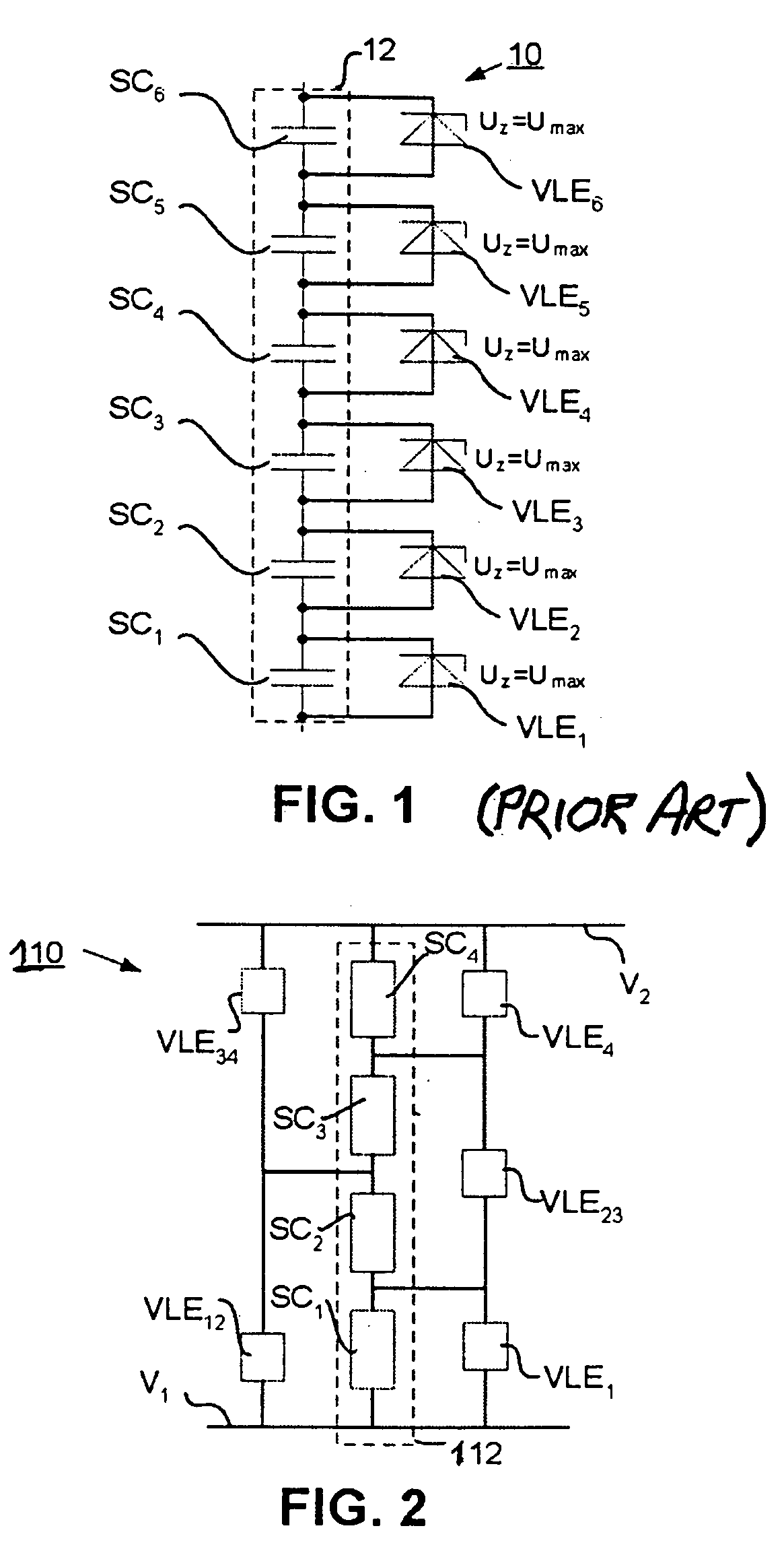
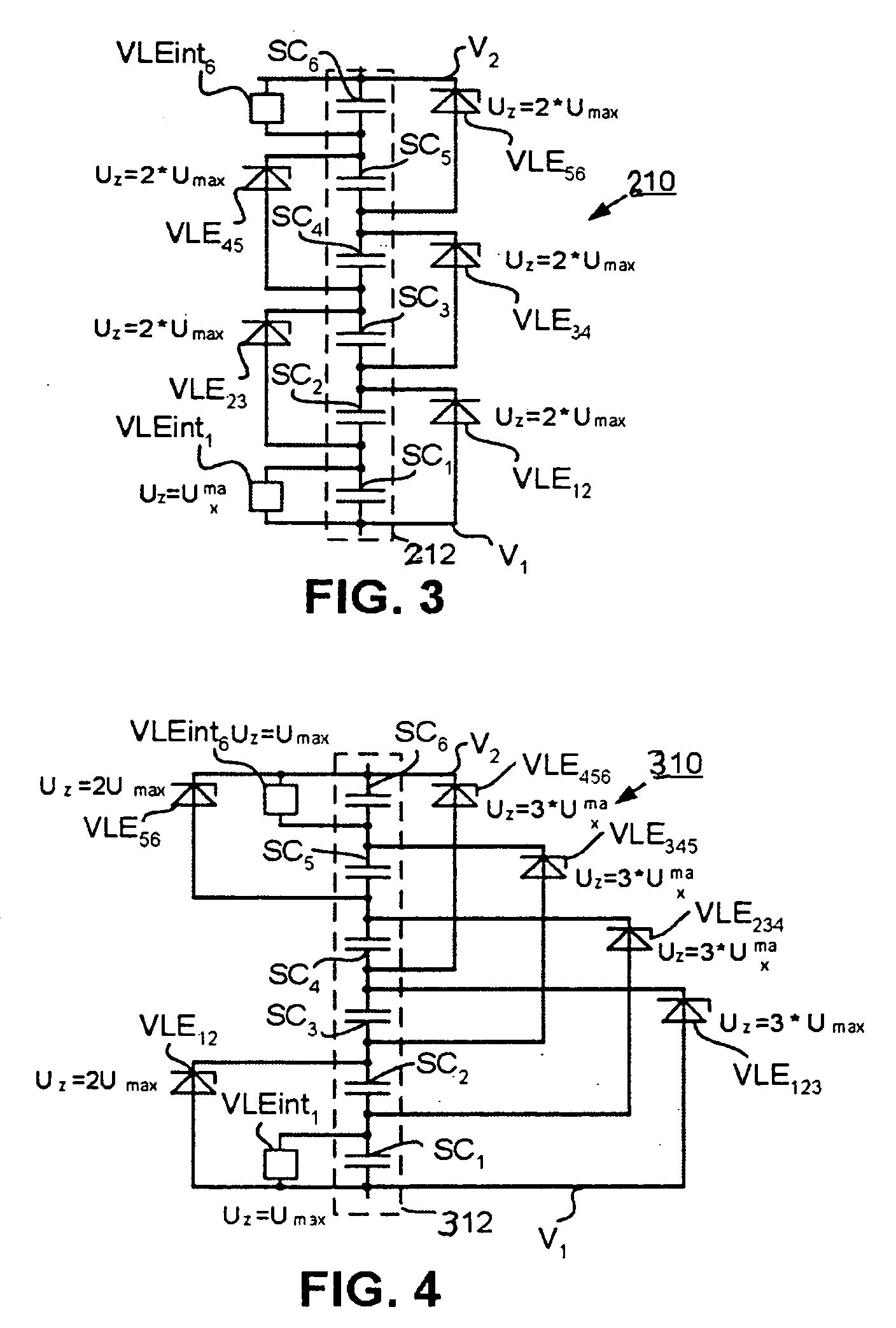
[0013] The series circuit can comprise any desired number of energy storage elements. The number “M” of the energy storage elements belonging to a combination of directly intercoupled energy storage elements can vary from circuit to circuit. Thus, in the case of a circuit of five energy storage elements, “M” can be selected to be equal to 2, 3, 4 or 5. A respective voltage-limiting element is connected in parallel with each combination of “M” energy storage elements. In addition, a respective voltage-limiting element is connected in parallel with the first and the nth energy storage element. Moreover, a respective voltage-limiting element is connected in parallel with all sub-combinations of at least two directly interconnected energy storage elements of the combination, which is connected to the first and the second potential. There thus results an intercalated arrangement of the voltage-limiting elements with respect to the energy storage elements with the characteristic that each energy storage element is bridged over by at least two, voltage-limiting elements and thus an over-voltage across an individual energy storage element is also recognized and prevented.
[0014] Since the maximum voltage of energy storage elements connected in series results from the sum of the maximum permissible voltages Umax, a Zener diode with a breakdown voltage corresponding with M·Umax can be employed for voltage limitation over a combination of “M” directly interconnected energy storage elements. The maximum permissible voltage Umax of super-capacitors lies at, for example, approximately 2.3 V to 2.5 V and thus the maximum permissible voltage across a combination of two super-capacitors lies at a maximum of 2·Umax=5 V. For this reason economic Zener diodes with a breakdown voltage of 5 V can be used for voltage limitation, these diodes providing an economic over-voltage protection.
[0015] The voltage-limiting element across the first and the last or nth energy storage element of the series circuit of energy storage elements has to have a breakdown voltage corresponding with the maximum permissible voltage of the bridged-over first or nth energy storage element. In one simple realization, a respective Zener diode of the breakdown voltage of 2.5 V is connected in parallel with the first and the last or nth energy storage element. This is disadvantageous to the extent that a Zener diode with the small breakdown voltage of 2.5 V has a relatively soft characteristic curve and a discharge current below the breakdown voltage. Accordingly, in an advantageous embodiment it is proposed to realize the voltage-limiting elements for the first and nth energy storage element by means of an integrated circuit with an over-voltage protection function. Due to the intercalated arrangement of the voltage-limiting elements and the additional safeguarding of the first and nth energy storage element an overvoltage is securely diverted from every energy storage element although only simple Zener diodes are used for the over-voltage protection. It is thereby made possible to provide an economic over-voltage protection for all energy storage elements of an energy storage module and thus to protect the energy storage module, in the case of losses in capacitance, against a possible total failure of energy storage elements.

Problems solved by technology

Since, however, the Zener diodes have for low voltages a gentle, relatively soft characteristic curve which already allows flow of a discharge current at voltages below the breakdown voltage this is disadvantageous for the overall efficiency of the energy storage module.

Method used


Image

  • Circuit arrangement for limitation of over-voltages in energy storage modules
  • Circuit arrangement for limitation of over-voltages in energy storage modules
  • Circuit arrangement for limitation of over-voltages in energy storage modules

Examples


Embodiment Construction

[0026]FIG. 1 shows a prior art energy storage module 10 with six super-capacitors SC1 to SC6, which are combined with one another to form a series circuit 12. A Zener diode VLE1-VLE6 serving as a voltage limitation device is connected in parallel with each super-capacitor SC1 to SC6 respectively. Each Zener diode VLE1-VLE6 has a breakdown voltage UZ corresponding with the maximum permissible voltage Umax of a super-capacitor. As previously explained, the maximum permissible voltage Umax of a super-capacitor amounts to 2.3 V to 2.5 V. This means that each Zener diode, which is also termed VLE (Voltage Limited Element), has a breakdown voltage UZ of 2.5 V. Different characteristic curves for Zener diodes are juxtaposed in FIG. 5. It can be recognized that the characteristic curves of the Zener diode in the region between 2 V and 3 V breakdown voltage have a gentle characteristic curve path. This means that even before attainment of the breakdown voltage UZ a current flows which reduce...


PUM


Abstract

A circuit for the limitation of over-voltages in energy storage modules having a series circuit of energy storage elements connected between a first potential and a second potential includes voltage-limiting elements associated with combinations of the energy storage elements. Where “M” is the maximum number of directly interconnected energy storage elements of a predetermined combination, wherein for M≧2 a voltage-limiting element is connected in parallel with each combination and a respective voltage-limiting element is connected in parallel with a first energy storage element connected to the first potential and with an nth energy storage element connected to the second potential. For M>2 a respective voltage-limiting element is connected in parallel with each sub-combination of at least two directly interconnected energy storage elements of the combination having an energy storage element connected to the first potential or to the second potential.

Description

BACKGROUND OF THE INVENTION [0001] The present invention relates to a circuit arrangement for the limitation of over-voltages in energy storage modules composed of energy storage elements. The circuit includes a series circuit of “n” energy storage elements, wherein the series circuit is connected between a first potential and a second potential and voltage-limiting elements are associated with the “n” energy storage elements. [0002] Energy storage modules serve for the storage of electrical energy. The storage capacity of conventional energy storage elements is usually smaller than the required total amount of energy to be stored. The maximum permissible voltage across an energy storage element is usually less than the voltage required for the application. Accordingly, several energy storage elements with smaller energy storage capacity are combined to form an energy storage module. Energy storage modules are usually designed as capacitors or accumulators. Super-capacitors (SCAP) f...

Claims


Application Information

Patent Timeline
IPC IPC(8): H01G9/28H01G11/00H01M10/44H02H7/16H02H7/18H02H9/04H02J7/00H02J7/34
CPCH02J7/345H02H7/16
Inventor GRUNDMANN, STEFFEN
Owner INVENTIO AG
Learn More