Objective lens for optical pick-up

a technology of optical pick-up and objective lens, which is applied in the field of objective lens for optical pick-up, can solve the problem that the objective lens cannot form a beam spot, and achieve the effect of suppressing aberrations insufficient amounts

Inactive Publication Date: 2005-12-22
HOYA CORP
View PDF18 Cites 18 Cited by
  • Summary
  • Abstract
  • Description
  • Claims
  • Application Information

AI Technical Summary

Benefits of technology

[0014] The present invention is advantageous in that it provides an objective lens which is configured to form a suitable beam spot on a data recording layer of each of a plurality of types of o

Problems solved by technology

However, as described above, a conventional objective lens (i.e., the objective lend disclosed in the document 1) is not designed for the new standard optical disc.
Therefore, if a beam of the blue laser is incident on the objective lens, the objective

Method used


Image

  • Objective lens for optical pick-up
  • Objective lens for optical pick-up
  • Objective lens for optical pick-up

Examples


first example

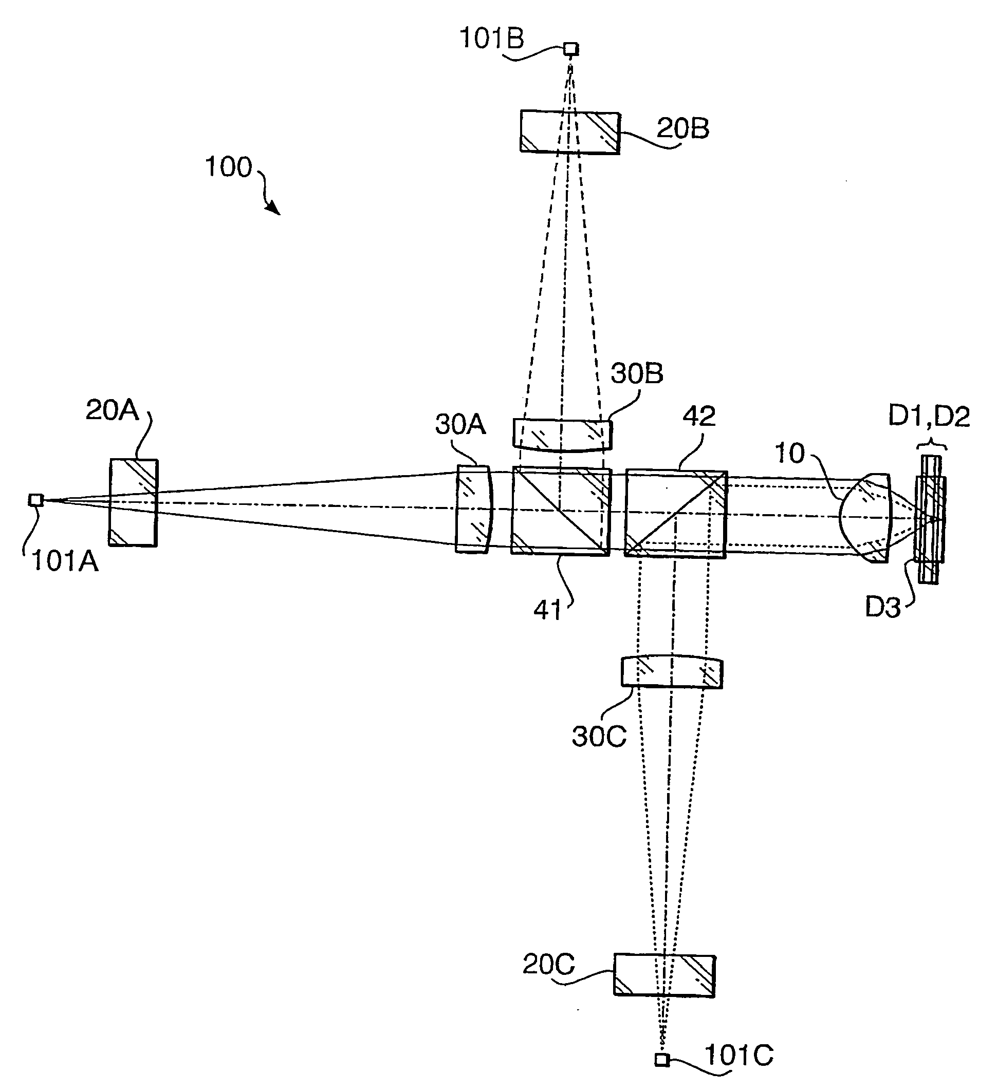
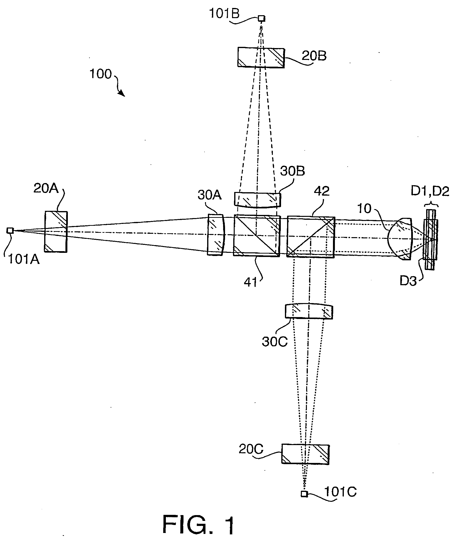
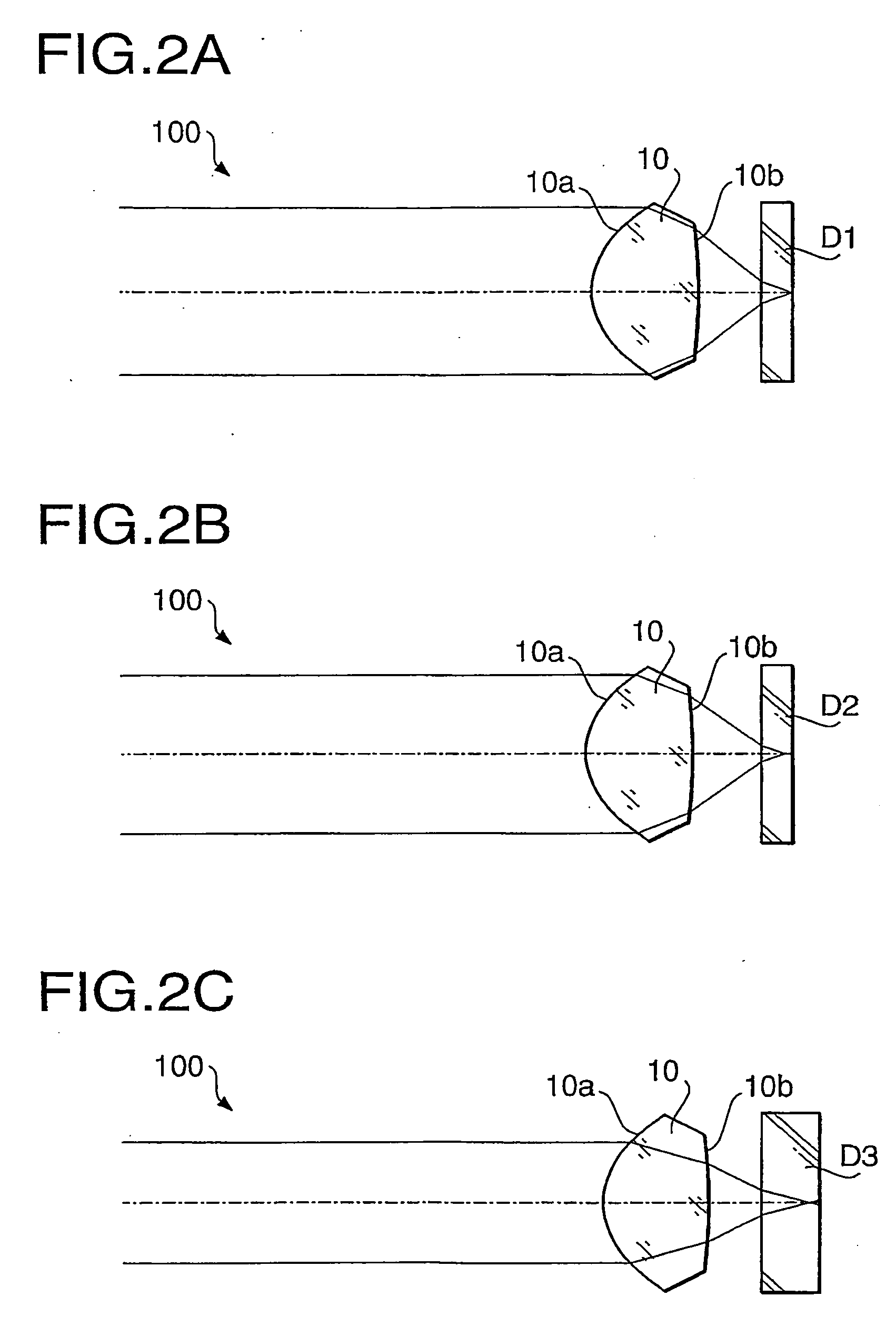
[0111] The optical pick-up 100 according to a first example has the configuration shown in FIGS. 1 and 2A to 2C. Performance specifications of the optical pick-up 100 and the objective lens 10 according to the first example are shown in Table 1.

TABLE 1First laserSecondbeamlaser beamThird laser beamDesign wavelength (nm)405657788Focal length ƒ (mm)3.0003.0993.118NA0.6500.6000.449magnification0.0000.0000.000

[0112] In Table 1 (and in the following similar Tables), the design wavelength is a wavelength suitable for the recording / reproducing operation of the optical disc, f represents a focal length (unit: mm) of the objective lens 10, NA represents the numerical aperture. In Table 1, the performance specifications are indicated with regard to each of the first laser beam (the optical disc D1), the second laser beam (the optical disc D2) and the third laser beam (the optical disc D3).

[0113] As can be seen from the values of the magnification in Table 1, each of the first to third lase...

second example

[0141] The optical pick-up 100 according to a second example has the configuration shown in FIGS. 1 and 2A to 2C. Performance specifications of the optical pick-up 100 and the objective lens 10 according to the second example are shown in Table 9.

TABLE 9FirstSecondlaser beamlaser beamThird laser beamDesign wavelength (nm)405657788Focal length ƒ (mm)3.0003.0993.118NA0.6500.6290.468magnification0.0000.0000.000

[0142] As can be seen from the values of the magnification in Table 9, each of the first to third laser beams is incident on the objective lens 10 as a collimated beam.

[0143] Table 10 shows a numerical configuration of the optical pick-up 100 when the optical disc D1 (the first laser beam) is used, Table 11 shows a numerical configuration of the optical pick-up 100 when the optical disc D2 (the second laser beam) is used, and Table 12 shows a numerical configuration of the optical pick-up 100 when the optical disc D3 (the third laser beam) is used. In the following Tables 10 to...

third example

[0166] Hereafter, the optical pick-up 100 according to a third example will be described. Since the optical pick-up according to the second example and the optical pick-up according to the third example are identical except for surface shapes of the objective lens 10, the specifications of the objective lens 10 and the numerical configurations shown in Tables 9 to 12 are also applied to the third example.

[0167] The objective lens 10 according to the third example has the specifications shown in Table 9. Therefore, the objective lens 10 according to the third example does not satisfy the conditions (2) and (3). Therefore, the objective lens 10 according to the third example is not provided with the third area 3. Each area formed on the surface 10a is defined as follows by the height h (mm) from the optical axis AX. [0168] Inner area 11 of first area 1: h≦1.11 [0169] Outer area 12 of first area 1: 1.11[0170] Second area 2: 1.46

[0171] As indicated above, in this example, h1a / h1 is 0.7...


PUM


Abstract

An objective lens for an optical pick-up which is used to record data to and/or to reproduce data from at least three types of optical discs by selectively using one of at least three light beams having different wavelengths is provided. When thicknesses of a first, second and optical discs are represented by t1, t2 and t3, respectively, a relationship t1≦t2<t3 is satisfied. When numerical apertures required for the first, second and third optical discs are represented by NA1, NA2 and NA3, respectively, a relationship NA1≧NA2>NA3 is satisfied. The first, second and third light beams are incident on the objective lens as substantially collimated light beams, respectively. In this configuration, at least one of surfaces of the objective lens includes a first area for attaining the numerical aperture required for recording data to and/or reproducing data from the third optical disc, and a second area located outside the first area. The first area includes an inner area including an optical axis of the objective lens, and an outer area located outside the inner area. The outer area is configured to converge the third light beam on a data recording layer of the third optical disc with an amount of an aberration being substantially zero. The objective lens satisfies a condition: 0.75<h1a/h1<0.87 . . . (1), where h1 represents an effective radius of the first area, and h1a represents an effective radius of the inner area.

Description

INCORPORATION BY REFERENCE [0001] This application claims priority of Japanese Patent Application No. 2004-181966, filed on Jun. 21, 2004, the entire subject matter of the application is incorporated herein by reference thereto. BACKGROUND OF THE INVENTION [0002] The present invention relates to an objective tens for an optical pick-up used for an optical disc drive, which is capable of recording data to and / or reproducing data from a plurality of types of optical discs having different recording densities and having different thicknesses of cover layers. [0003] There are various types of optical discs on which digital information is recorded at various densities, respectively. For example, a DVD (digital versatile disc) has a recording density higher than that of a CD (compact disc) or a CD-R (CD Recordable) and has a cover layer thinner than that of the CD or CD-R. [0004] When the recording / reproducing operation for the DVD having a higher recording density is performed, a smaller...

Claims


Application Information

Patent Timeline
IPC IPC(8): G11B7/00G11B7/125G11B7/135
CPCG11B7/1275G11B7/1367G11B2007/0006G11B7/139G11B7/13922G11B7/1374
Inventor KOREEDA, DAISUKEMARUYAMA, KOICHI
Owner HOYA CORP
Why Eureka
Try Eureka