Optical pick-up

Inactive Publication Date: 2008-03-27
ASAHI KOGAKU KOGYO KK
View PDF4 Cites 12 Cited by
  • Summary
  • Abstract
  • Description
  • Claims
  • Application Information

AI Technical Summary

Benefits of technology

[0007]In consideration of the above, the present invention is advantageous in that there is provided an optical disc drive with which generation of spherical aberration can be well suppressed, and a driving mechanism for a beam expander to compe

Problems solved by technology

However, in order to achieve such a high NA with a single-element plastic lens, generation of spherical aberration becomes significantly large as the temperature changes.
However, the technology described in the above publication has a configuration where an objective lens is designed so that wavefront aberration becomes zero at a specific setting temperature, and when an actual temperature of the objective lens is shifted

Method used


Image

  • Optical pick-up
  • Optical pick-up
  • Optical pick-up

Examples


first embodiment

[0028]Hereinafter, an optical pick-ups according to embodiments of the invention will be described with reference to the accompanying drawings.

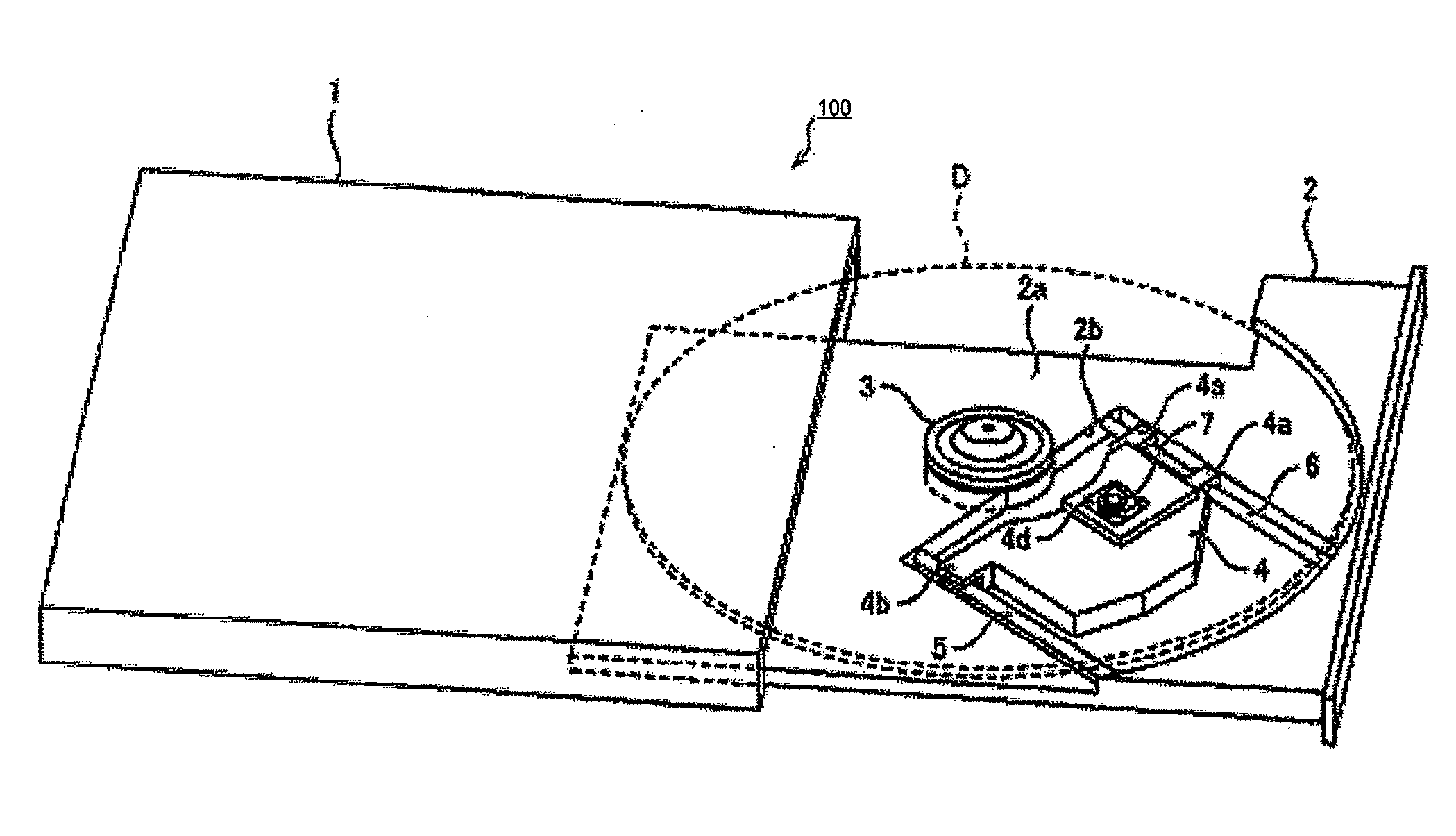
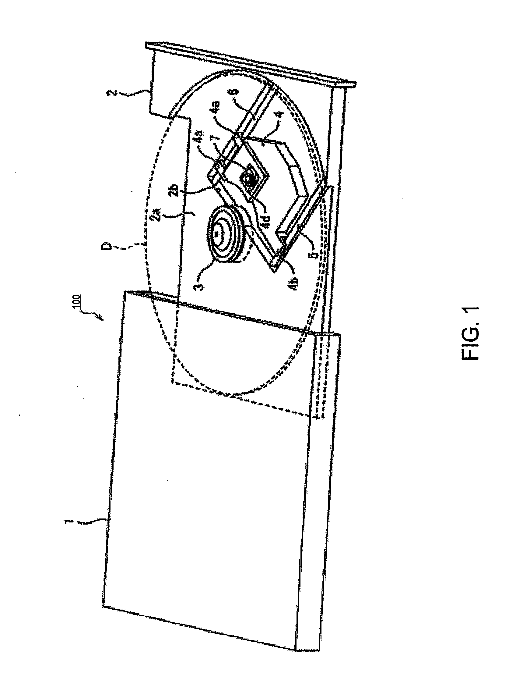
[0029]FIG. 1 is a perspective view of an optical disc drive 100 according to the embodiment of the invention. As shown in FIG. 1, the optical disc drive 100 includes a thin box-type casing 1 which is to be assembled in a personal computer (not shown), a video recorder or the like, and a tray 2 which is ejectable / retractable with respect the casing 1. When the tray 2 is ejected from the casing 1, an optical disc D can be mounted or dismounted. When the tray 2 is retracted into the casing 1, the tray 2 is completely accommodated in the casing 1 and an opening of the casing 1, through which the tray 2 is ejected, is closed.

[0030]Further, according to the embodiment, in order to make the entire optical disc drive 100 thin, major components such as a spindle 3 and a carriage 4 to perform essential functions of the optical disc drive 100 are mounte...

second embodiment

[0066]Next, a second embodiment according to the invention will be described. Compared to the first embodiment, the second embodiment is different in that the heater 21 is divided into four heater elements 40-43, and each of the four elements is configured to generated heat individually. Each of FIGS. 8-10, which shows a configuration of the second embodiment corresponds to each of FIG. 2-4 relating to the above described first embodiment.

[0067]Layouts of the heater elements 40-43 on the upper surface of the lens holder 12 in the second embodiment are shown in FIG. 9 and FIG. 10. That is, in the second embodiment, similar to the first embodiment shown in FIG. 3 and FIG. 4, a lens holder with a frame 12c is used. Then, the heater elements 40-43 which are rounded to have a outer shape of quasi-rectangular solid are fixed individually on four edges of the frame 12c on the upper surface of the lens holder 12 (i.e., on each of the focusing magnets 18, 18 and positions next to the frame 1...

third embodiment

[0076]A third embodiment according to the invention will be described. Compared to the first embodiment, the configuration of the third embodiment is different in that the heater 21 is installed inside the penetrated opening 12b and the light source side end of the penetrated opening 12b is closed with a cover glass 44. Each of FIGS. 13, 14 and 16 which shows a configuration of the third embodiment corresponds to each of FIG. 2-4 relating to the above described first embodiment. Further, FIG. 15 is a view of the objective lens actuator 10, with parts broken away for the sake of clarity and shows the interior of the penetrated hole 12b of the lens holder.

[0077]As shown in FIG. 14, on the upper surface of the lens holder 12, no heater, etc., is installed. Instead, as shown in FIG. 15 and FIG. 16, on the inner surface of the penetrated opening 12b of the frame 12c, only vicinity of the opening end on the disc side (upper side in FIG. 16B) has a inner diameter which is almost the same a...


PUM


Abstract

According to an aspect of the invention, there is provided an optical pick-up for an optical disc drive, which is provided with an objective lens configured to converge a laser beam emitted from a laser source on a recording surface of an optical disc, spherical aberration caused by the objective lens being compensated at a predetermined setting temperature of the objective lens, a heating unit configured to be driven to heat the objective lens, a spherical aberration detection unit which detects amount of spherical aberration caused by the objective lens, and a driving unit that drives the heating unit in accordance with the amount of the spherical aberration detected by the spherical aberration detection unit, the driving unit driving the heating unit when the spherical aberration detected by the spherical aberration detection unit is positive, the driving unit stopping driving the heating unit when the spherical aberration is zero or negative.

Description

BACKGROUND OF THE INVENTION [0001]The present invention relates to an optical pick-up which emits laser beam to an optical disc for writing information on a recording surface and / or reading information recorded on the recording surface.[0002]An optical pick-up is generally used in various optical disc drives configured to read out information recorded on an optical disc such as a CD (Compact Disc) or a DVD (Digital Versatile Disc) and / or write information on the optical disc. Generally, the optical pick-up is configured to receive a laser beam emitted by a laser source and converge the laser beam onto a recording surface of an optical disc.[0003]A size of each pit formed on the optical disc is the same order of a wave length of the laser beam to be used in order to maximize recording density on the optical disc. For this purpose, it is known that spherical aberration meets a certain requirement, which is known as Marechal's limit. According to Marchal's limit, the spherical aberrati...

Claims


Application Information

Patent Timeline
IPC IPC(8): G11B5/09
CPCG11B7/13925G11B7/1374
Inventor NISHIKAWA, HIROSHITAKISHIMA, SUGURUHONMA, RYOSEIKANAZAWA, HIROSHI
Owner ASAHI KOGAKU KOGYO KK
Why Eureka
Try Eureka