

Moving image coding apparatus
a coding apparatus and moving image technology, applied in the field of moving image coding apparatus, can solve the problems of excessive increase in coding processing time or waste of electric power, and achieve the effect of facilitating the selection of the optimal intra-prediction mod
- Summary
- Abstract
- Description
- Claims
- Application Information
AI Technical Summary
Benefits of technology
Problems solved by technology
Method used
Image

Examples
first embodiment
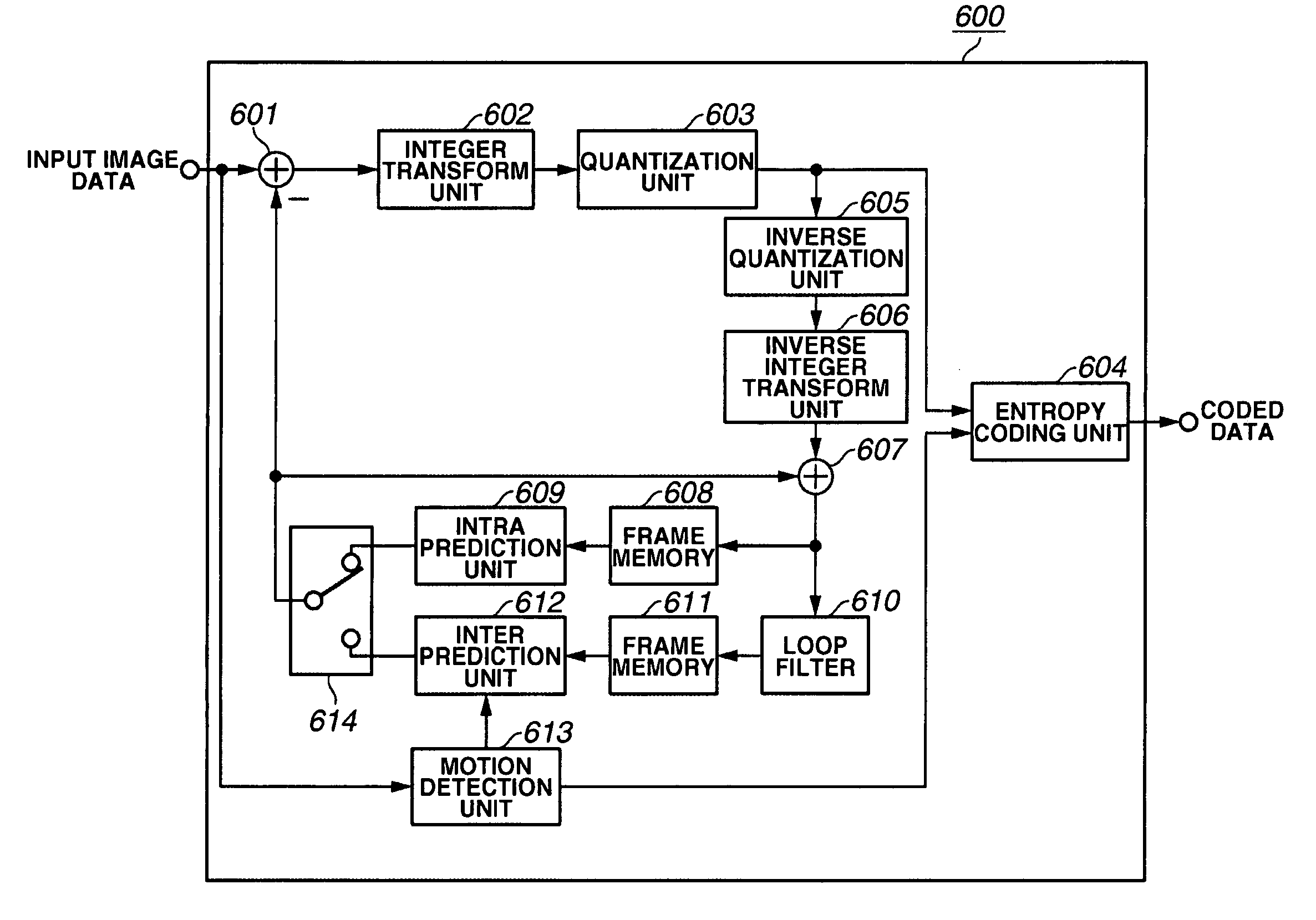
[0037]FIG. 6 is a block diagram showing the configuration of an image coding apparatus 600 according to a first embodiment of the invention. The image coding apparatus 600 includes a subtracter 601, an integer transform unit 602, a quantization unit 603, an entropy coding unit 604, an inverse quantization unit 605, an inverse integer transform unit 606, an adder 607, frame memories 608 and 611, an intra prediction unit 609, a loop filter 610, an inter prediction unit 612, a motion detection unit 613, and a switch 614. The image coding apparatus 600 is configured to perform processing for coding input image data to output the coded data.
[0038] The coding process in the image coding apparatus 600 shown in FIG. 6 is described next. The image coding apparatus 600 performs processing for coding according to the H.264 standard. Further, the image coding apparatus 600 divides input moving image data into blocks and performs processing for every block.
[0039] Initially, the subtracter 601 ...
second embodiment
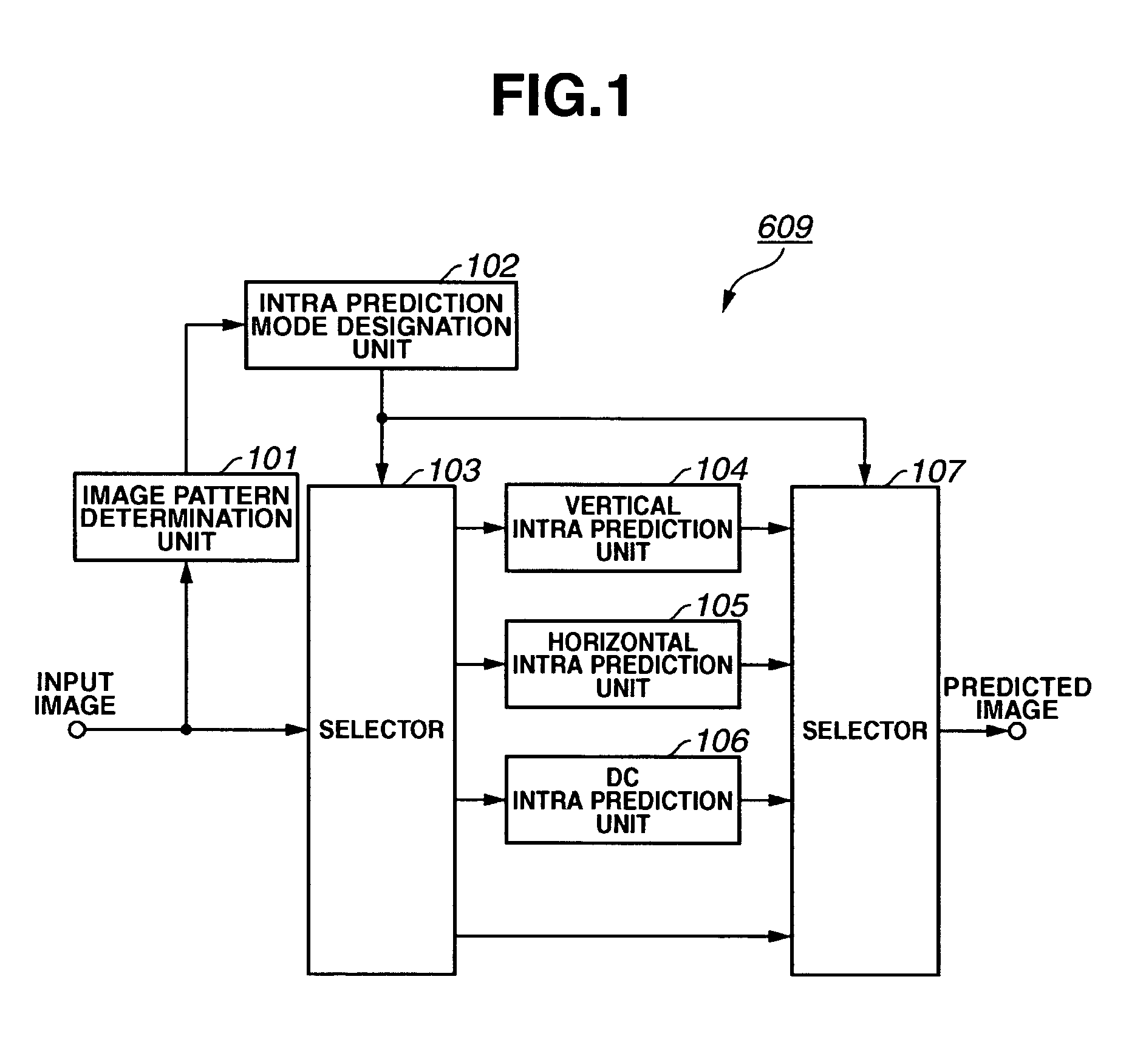
[0097] A second embodiment of the invention relates to an example of modification of the image pattern determination unit 101 described in the first embodiment shown in FIG. 1. In the second embodiment, the image pattern determination unit 101 is configured to determine an image pattern using a method for applying filtering to an input image, instead of using the Hadamard transform method. The construction and operation of parts other than the image pattern determination unit 101 are the same as those described in the first embodiment and are, therefore, omitted from description here.
[0098] The image pattern determination unit (filtering unit) 101 in the second embodiment determines an image pattern, such as an edge, by applying a difference filter to an input image of each block and evaluating the magnitude of an edge intensity value obtained. As the difference filter for use in the image pattern determination unit 101, for example, an operator is used. The operator is a matrix ha...
third embodiment
[0102]FIG. 14 is a block diagram showing the configuration of an image coding apparatus 1400 according to a third embodiment of the invention. The image coding apparatus 1400 includes a subtracter 601, an integer transform unit 602, a quantization unit 603, an entropy coding unit 604, an inverse quantization unit 605, an inverse integer transform unit 606, an adder 607, frame memories 608 and 611, a loop filter 610, an inter prediction unit 612, a motion detection unit 613, a switch 614, and an intra prediction unit 615. The image coding apparatus 1400 is configured to perform processing for coding input image data to output the coded data.
[0103] The coding process in the image coding apparatus 1400 shown in FIG. 14 is described below. The image coding apparatus 1400 performs processing for coding according to the H.264 standard. Further, the image coding apparatus 1400 divides input image data into blocks and performs processing for every block.
[0104] In the block diagram of FIG....
PUM
 Abstract
Description
Claims
Application Information