The conventional fan
system requires unnecessarily large amounts of power to achieve any substantial improvements in air flow and distribution efficiency.
Other problems also exist with conventional condensers include noisy operation with the conventional
fan blade designs that can disturb home owners and neighbors.
However, little effort has examined potential improvements to the
system fans.
Heat transfer to the outdoors with conventional fans is adequate, but power requirements are unnecessarily high.
Although more efficient ECM motors are available, these are quite expensive.
Over the past several years, a number of studies have examined various aspects of air conditioner condenser performance, but little examining specific improvements to the outdoor fan unit.
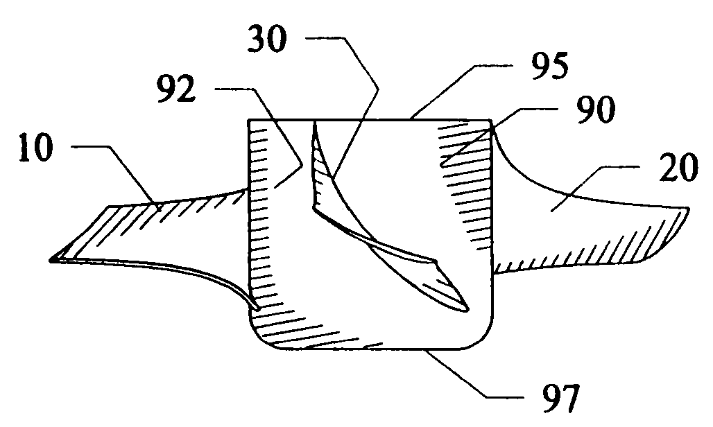
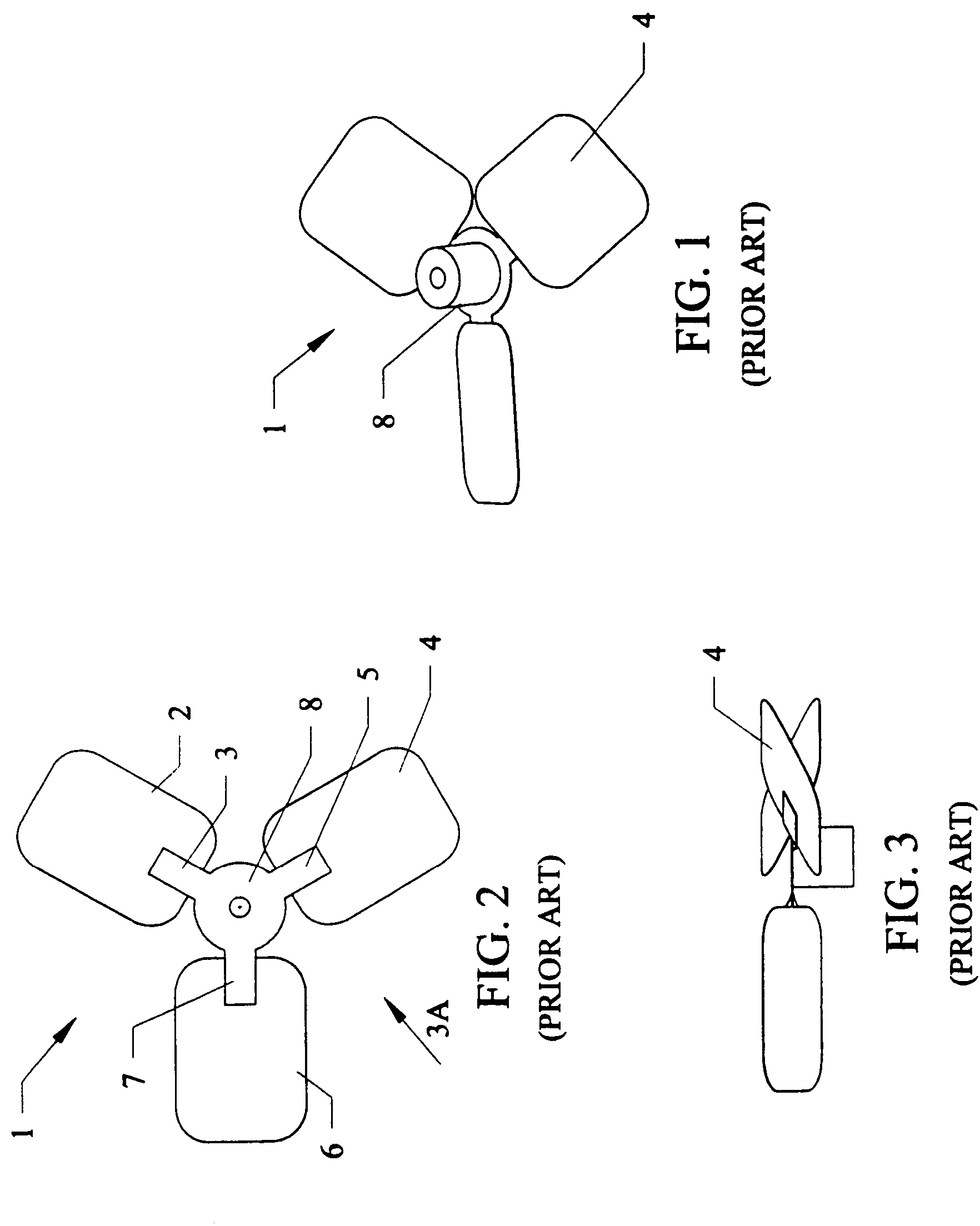
Conventional fan blades used in most AC condensers are stamped
metal blades which are cheap to manufacture, but are not optimized in terms of providing maximum air flow at minimum input
motor power.
Moreover, the saturation of households using this equipment has dramatically changed over the last two decades.
Many patents have been proposed over the years for using fan blades but fail to deal with specific issues for making the air conditioner condenser fans more efficient for flow over the typical motor rotational speeds.
Such a design would not be appropriate for application for air condition condenser fan where much large volumes of air (e.g. 2500 cfm) must be moved at fan rotational velocities of 825-1100 rpm.
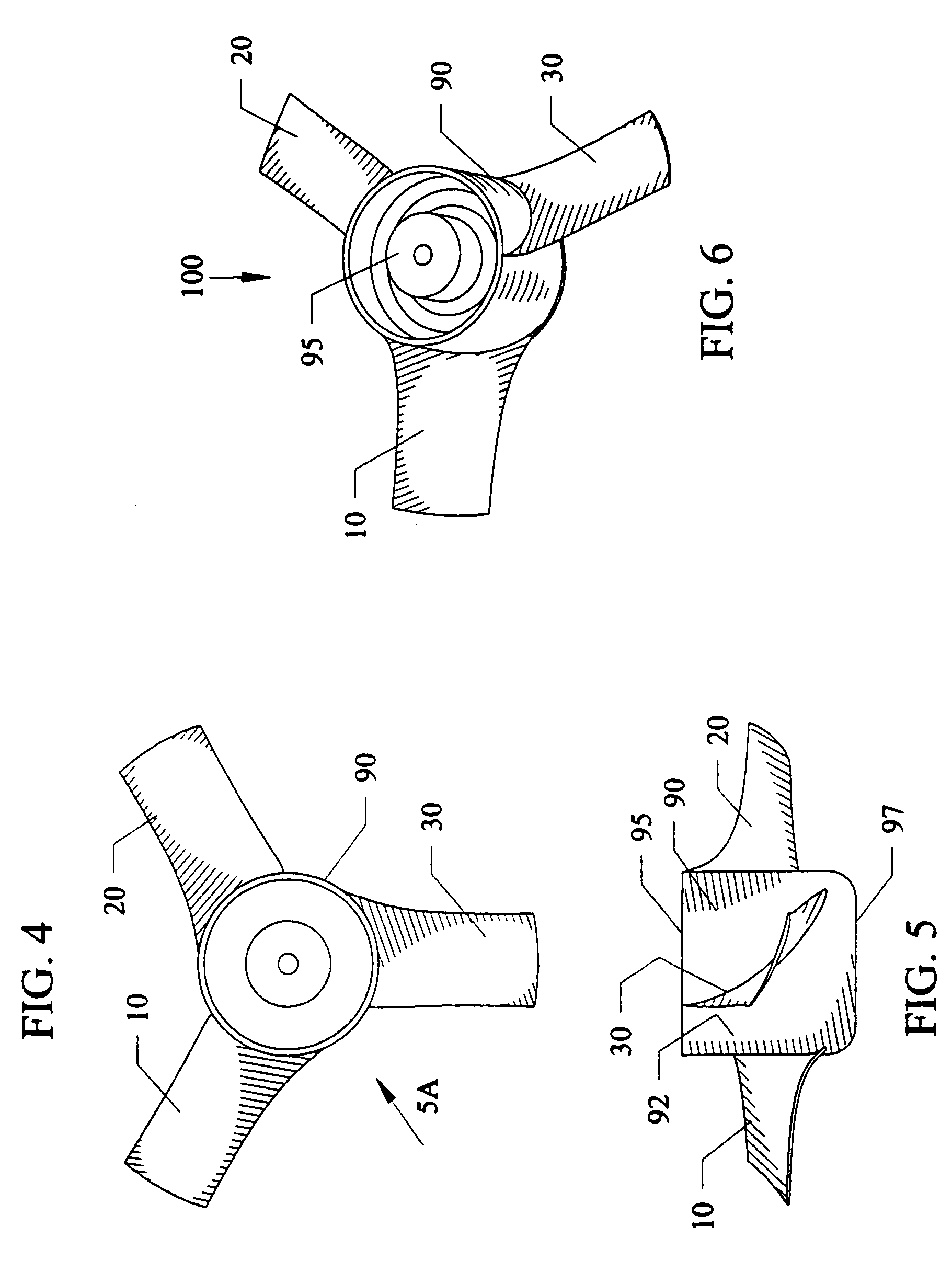
The fans feature effective air foils, but the specific blade shape, chord, taper and twist are not optimized for the specific requirements for residential
air conditioning condensers (825-1100 rpm with 2000-4800 cfm of air flow against low static pressures of 0.10-0.15 IWC) Thus, the cross sectional shapes and general design of this device are not relevant to the requirements for effective fans for air conditioner condensers.
It also does not achieve sufficient flow as the Neely device produces a flow of 24.6-25.7 cubic meters per minute or 868 to 907 cfm —only half of the required flow for a typical residential air conditioner condenser (Table 1).
Thus, the Neely device would not be use relevant for condenser fan designs which need optimization of the blade characteristics (taper, twist and airfoil) for the flow (approximately 2500 to approximately 4500 cfm) and rotational requirements of approximately 825 to approximately 1100 rpm.
The prior art air conditioning condenser systems and condenser blades do not consistently provide for saving energy at all times when the air conditioning
system operates and do not provide dependable electric load reduction under peak conditions.

