Hole guide for mini and standard dental implants

a dental implant and guide technology, applied in the field of dental implants, can solve the problems of bone overheating, loss of implants, devitalization of adjacent teeth, etc., and achieve the effect of avoiding the serious danger of damaging structures

Inactive Publication Date: 2005-12-22
SUSSMAN HAROLD I +1
View PDF8 Cites 80 Cited by
  • Summary
  • Abstract
  • Description
  • Claims
  • Application Information

AI Technical Summary

Benefits of technology

[0018] The same or a different guide of the invention is then used to locate and drill the next lateral hole in the jaw. Four holes can be created in this way without coming close to the MF or mental foramens of the lower jaw in particular, and thus avoiding the serious danger of damaging structures in this sensitive area.

Problems solved by technology

Although dental implants have many benefits, particularly where a patient is missing teeth over large portions of the mouth, various complications can follow implant placement, especially to adjacent teeth.
The bone may be overheated during implant surgery, for example, and this can devitalize an adjacent tooth.
Endodontic lesions can also form which compromise the implant fixture by preventing integration of the bone around the fixture (osseointegration), causing loss of the implant.
Another problem involves a patient with no teeth or so called edentulous patients.
A further problem facing the implantologist is the importance of avoiding any invasion of the jaw in the area of the mental foramens or MF, which exist on opposite sides of the lower jaw.
Within the confines of the mouth, it is also very difficult to accurately align a dental bur for drilling the crucial initial pilot hole of about 2 mm in diameter needed for a standard implant of about 3 to 4 mm in diameter.
Even with x-rays, however, it is difficult for a dentist to accurately align the bur without some help.
A complex and time consuming technique for properly aligning the initial implant hole is disclosed in U.S. Pat. No. 5,015,183.
Another problem associated with the use of a stent is that when a surgical stent is fabricated from an alginate jaw impression, as is commonly done, the registration of the surface jaw tissue does not always reflect the underlying topography of the jaw bone where the implant is to be placed.

Method used


Image

  • Hole guide for mini and standard dental implants
  • Hole guide for mini and standard dental implants
  • Hole guide for mini and standard dental implants

Examples


Embodiment Construction

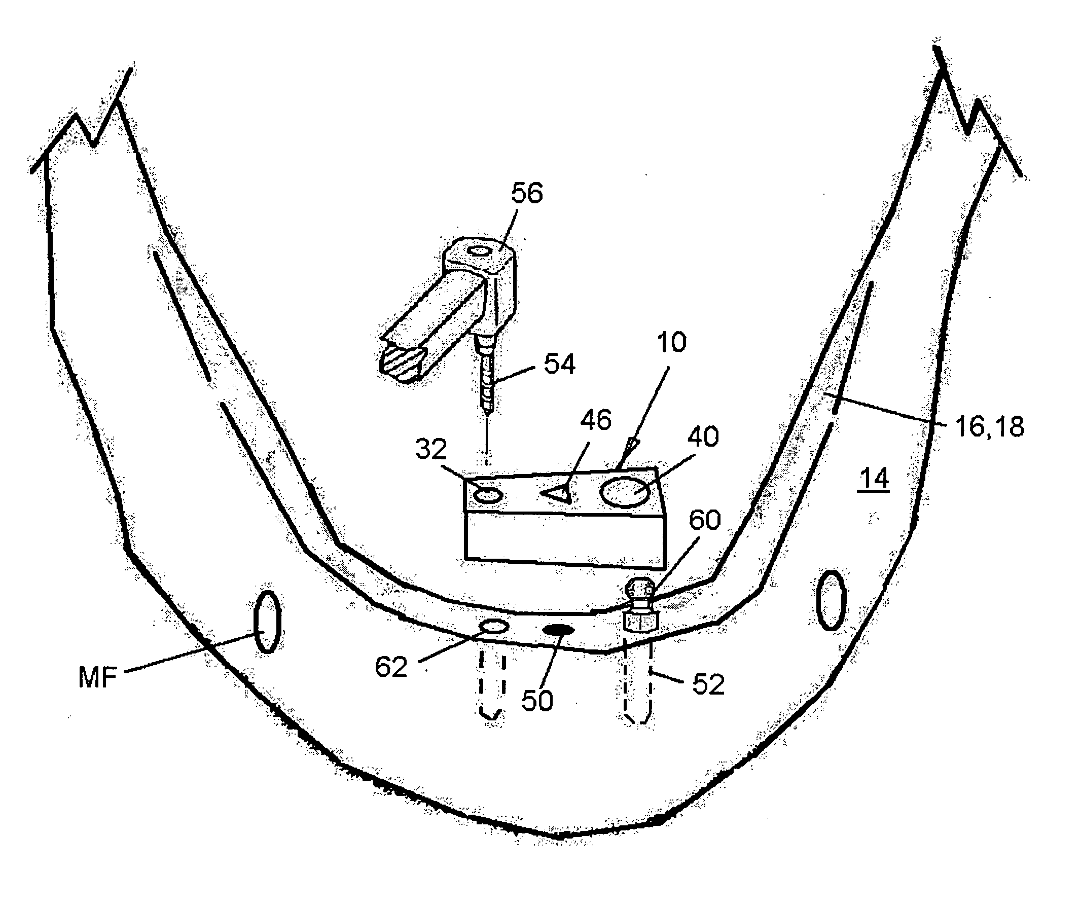
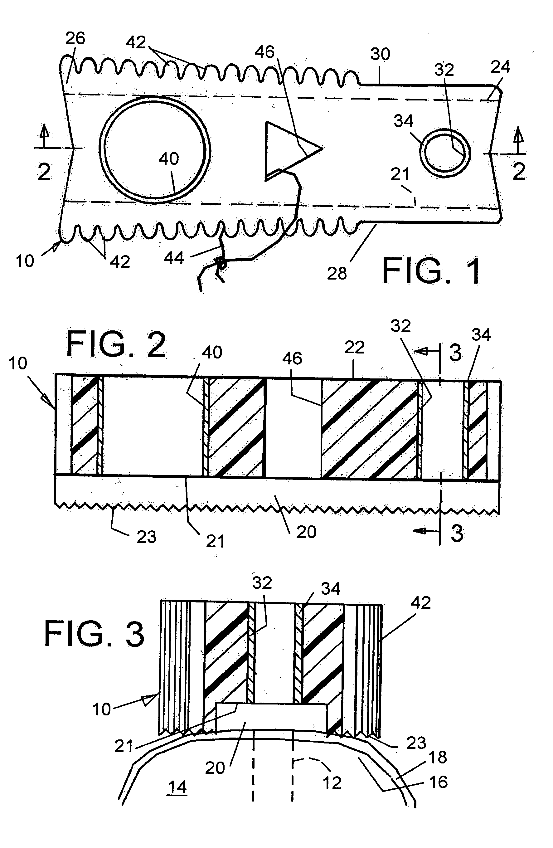
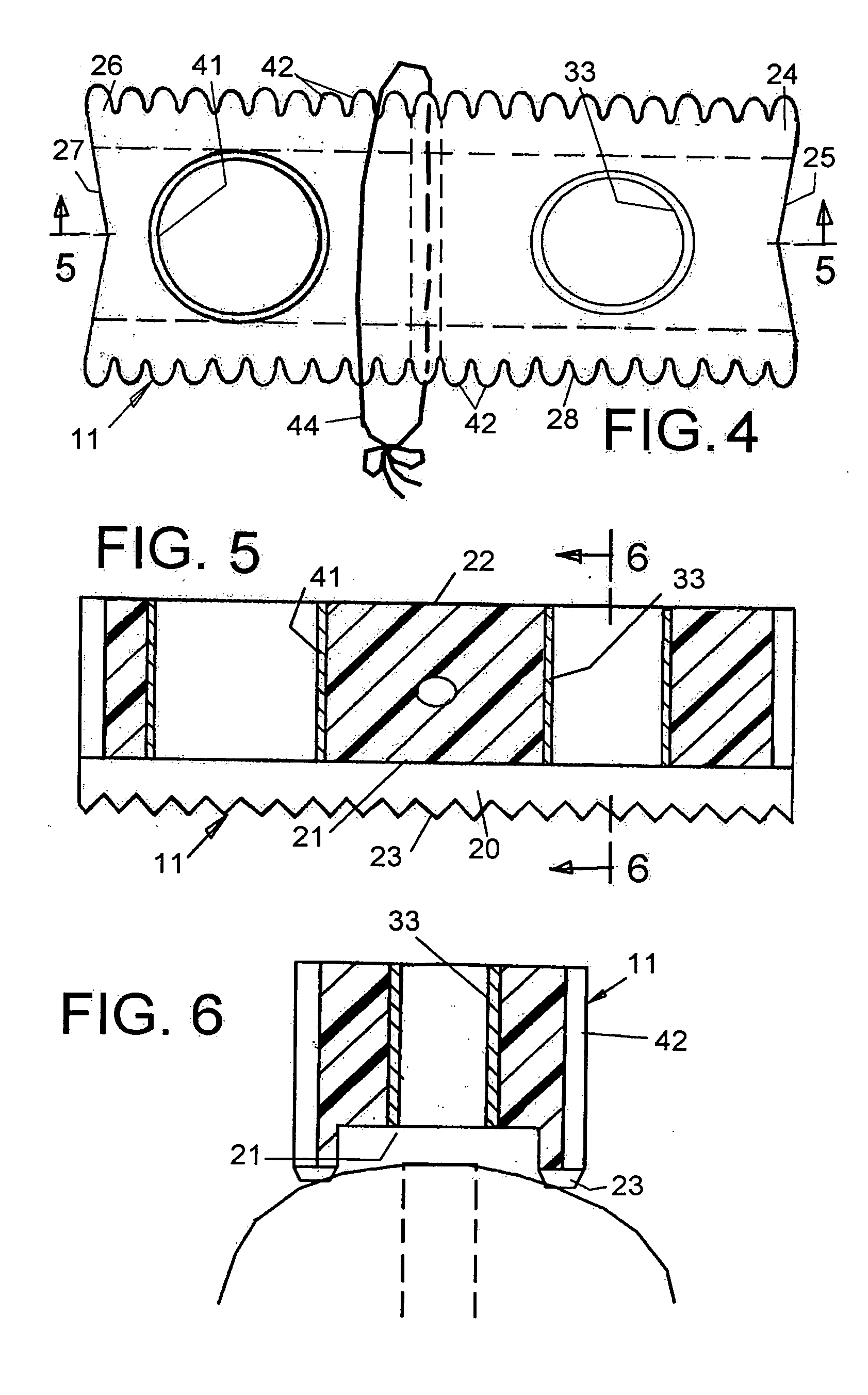
[0036] Referring now to the drawings in which like reference numerals are used to refer to the same or functionally similar elements, FIGS. 1, 2 and 3 illustrate an implant hole guide 10 for use in drilling a hole 12 in a jaw bone 14 in preparation for receiving a dental implant. The jaw bone has a ridge 16 for receiving an entry opening of the hole 12 to be drilled, and may be covered by gum tissue 18 for certain procedures for installing mini-implants, or may have the gum tissue temporarily moved aside for installing standard implants as will be explained later.

[0037] The guide member 10 has an inner surface 20 for engaging the ridge of the jaw bone when the guide member is engaged onto the jaw bone, and an opposite outer surface 22. The guide 10 also has a first end 24 and an opposite second end 26. The guide has a buccal surface 28 and an opposite lingual surface 30, however, these surfaces are interchangeable depending on the orientation of the guide when in use.

[0038] Guide ...


PUM


Abstract

An implant hole guide is used for drilling a hole in jaw bone for a dental implant. A guide member of the guide has opposite ends and opposite surfaces, one being adapted to engage a jaw bone adjacent the site of a hole to be drilled. A guide bore extends in the guide member adjacent one end for guiding the drill. A second bore is spaced from the first bore in the guide member and either engages a previous implant to properly locate the first bore over a further hole site on the jaw, or for guiding the drilling of another implant hole in the jaw. The bores are parallel to each other and are spaced by a minimum center-to-center implant distance sufficient to maintain at least 3 mm of jaw bone between adjacent implant receiving holes in the jaw bone.

Description

FIELD AND BACKGROUND OF THE INVENTION [0001] The present invention relates generally to dental implants, and in particular to a new and useful dental implant guide which provides a dentist with an intuitive and effective device for properly positioning and drilling the holes needed for various types of dental implants. [0002] Since 1981, dental root form implants have become a standard procedure for replacing missing teeth. Unlike other dental procedures such as crown and bridge work, root canals and the like, which utilize at least part of the original tooth as a foundation for the tooth replacement, implants require the drilling of holes directly into the bone of the jaw. [0003] Although dental implants have many benefits, particularly where a patient is missing teeth over large portions of the mouth, various complications can follow implant placement, especially to adjacent teeth. The bone may be overheated during implant surgery, for example, and this can devitalize an adjacent ...

Claims


Application Information

Patent Timeline
Patent Type & Authority Applications(United States)
IPC IPC(8): A61C3/02A61C8/00
CPCA61C1/084
Inventor SUSSMAN, HAROLD I.HADWIN, STEPHEN J.
Owner SUSSMAN HAROLD I
Why Eureka
Try Eureka