
Shoe assembly for power tool power tool incorporating such assembly

a technology of power tools and shoe assemblies, which is applied in the direction of power driven reciprocating saws, manufacturing tools, metal sawing devices, etc., can solve the problems of awkward movement of the shoe, and the jerky movement of the sho

Inactive Publication Date: 2005-12-29
BLACK & DECKER INC
View PDF26 Cites 21 Cited by
  • Summary
  • Abstract
  • Description
  • Claims
  • Application Information

AI Technical Summary

Benefits of technology

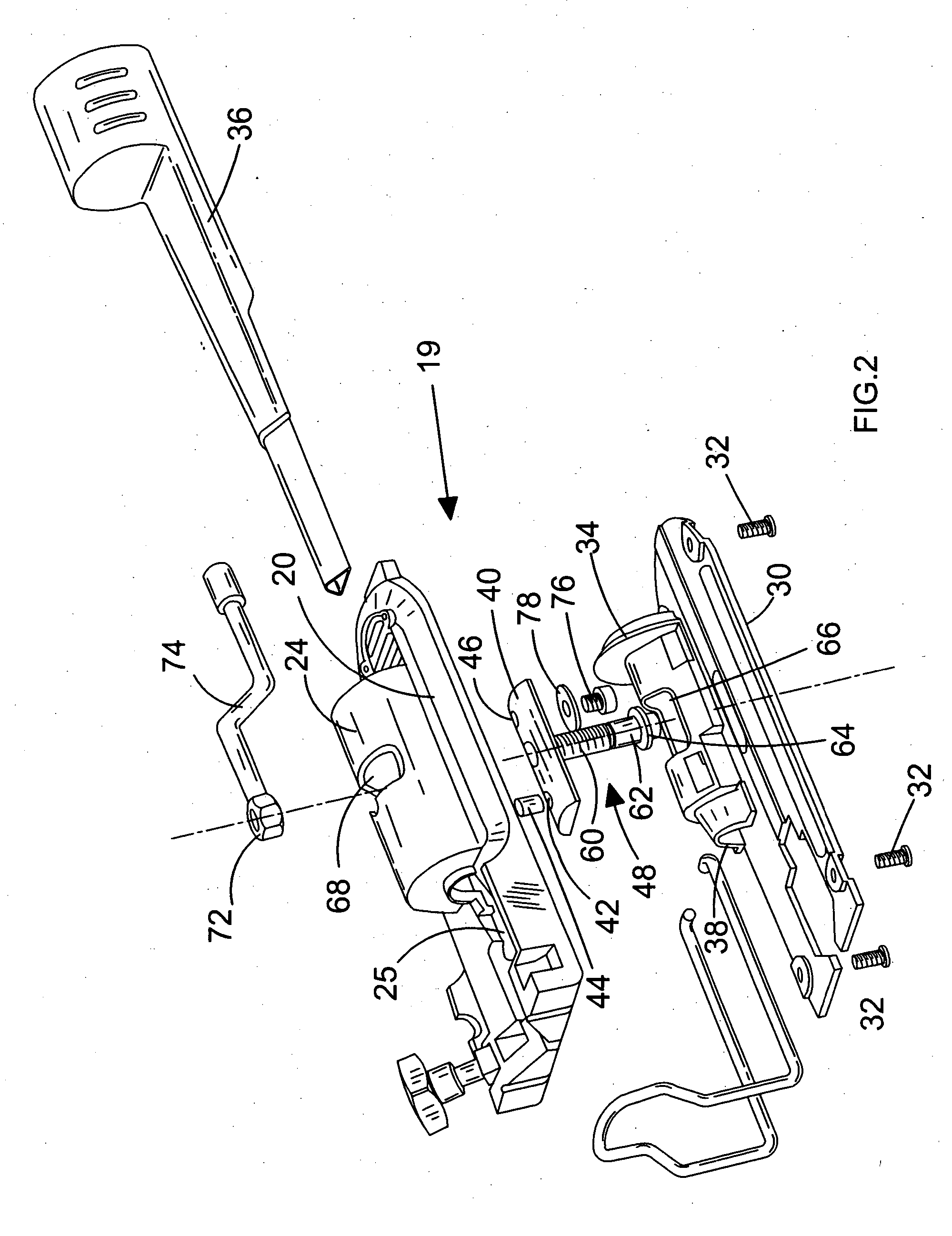
[0009] By providing a shoe portion with at least one recess provided on a surface facing away from the housing of the tool in use, engaging at least one resiliently displaceable projection, this provides the advantage of making the pivoting movement of the shoe smoother, and less awkward for the user, than in prior art devices. In a preferred embodiment, at least one said resiliently displaceable projection comprises a respective spring-loaded ball bearing. This provides the advantage that the ball bearing slides easily in and out of engagement with the respective recesses as pressure is applied to the shoe.
[0010] In a preferred embodiment, at least one said spring-loaded ball bearing, at least one said clamp plate having a respective arcuate upper surface adapted to slidably engage the shoe portion such that at least one corresponding said ball bearing can selectively resiliently engage each of a plurality of said recesses of the shoe portion in response to a user pivoting said housing relative to said shoe member. This provides the advantage of increasing the strength of the link between the shoe and the housing.
[0011] The assembly may further comprise first locking means adapted to lock said shoe portion in a predetermined orientation relative to the mounting portion. This provides the advantage of preventing unwanted pivoting of the shoe, and increasing the safety of the assembly. In a preferred embodiment, said first locking means comprises at least one first bolt adapted to lock at least one said clamp plate to the shoe portion. In a preferred embodiment, rotation of at least one said first bolt in a first sense causes at least one corresponding said clamp plate to disengage from the surface of said shoe potion, and rotation in the opposite sense causes at least one corresponding said clamp plate to engage the surface of said shoe portion in order to lock the clamp plate to the shoe portion.
[0012] The first locking means may further comprise at least one nut rotatably mounted to said housing and adapted to receive at least one said first bolt. In a preferred embodiment, at least one said nut comprises a respective lever for rotation of said nut relative to said housing. This provides the advantage of providing easy rotation of the nut for the user.
[0013] In a preferred embodiment the assembly further comprises second locking means adapted to prevent rotation of at least one said first bolt relative to a said clamp plate engaged by said bolt. This provides the advantage of locking the nut lever in place, such that the user accidentally moving the lever cannot loosen the shoe assembly. Said second locking means may comprise at least one second bolt and at least one washer, at least one said second bolt received in at least one said clamp plate such that in a first position, at least one said washer abuts a said first bolt and prevents rotation of said first bolt, and such that in a second position rotation of the first bolt is permitted.
[0015] In a preferred embodiment, the tool further comprises dust extraction means adapted to remove dust produced by the action of said working member on a workpiece. This provides the advantage removing dust from the vicinity of the tool and the user. Said dust extraction means may comprise a tube projecting from said shoe portion adapted to be connected to a source of suction.

Problems solved by technology

This prior art bevel-cutting jigsaw suffers from the drawback that the ball bearings push the shoe away from the housing, making the pivoting movement of the shoe jerky and awkward.

Method used


Image

  • Shoe assembly for power tool power tool incorporating such assembly
  • Shoe assembly for power tool power tool incorporating such assembly
  • Shoe assembly for power tool power tool incorporating such assembly

Examples


Embodiment Construction

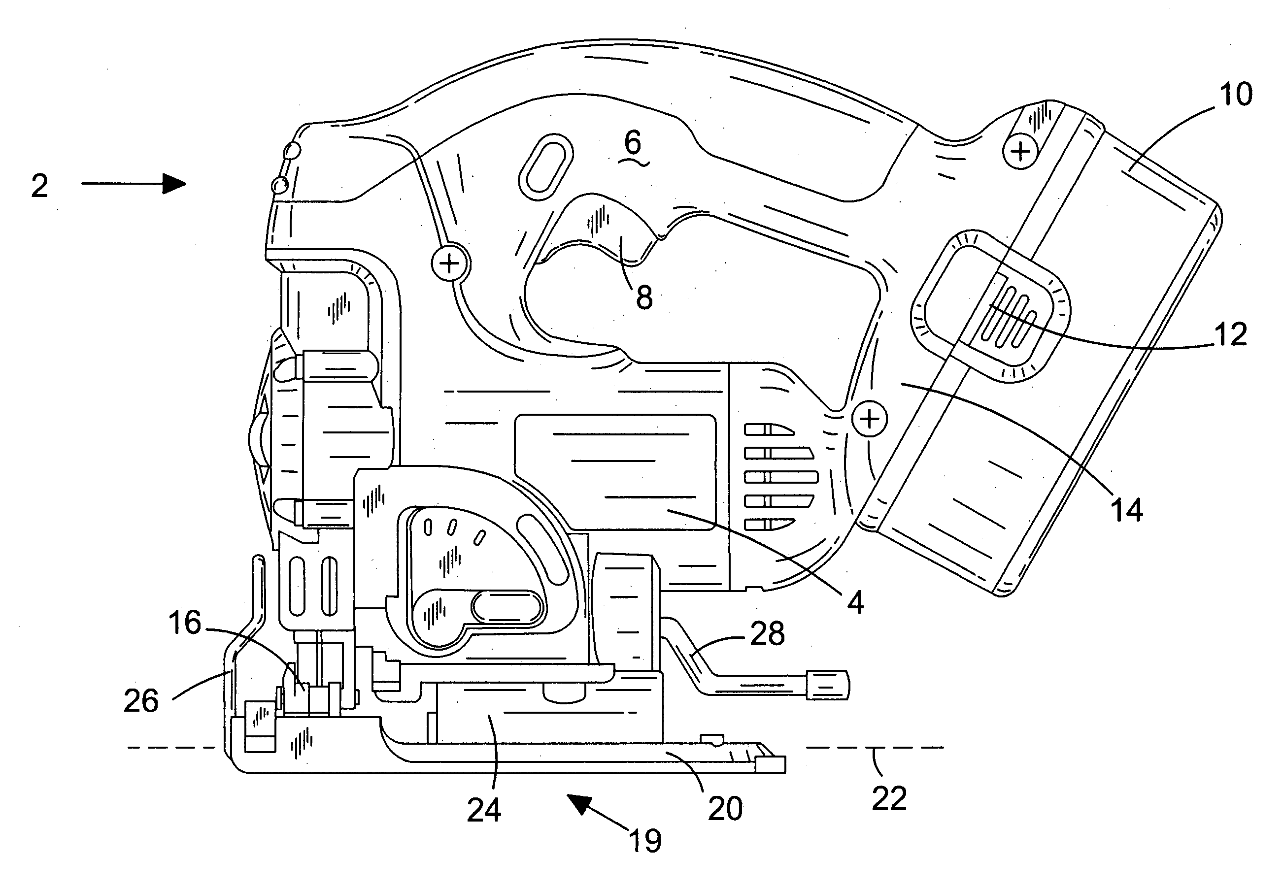
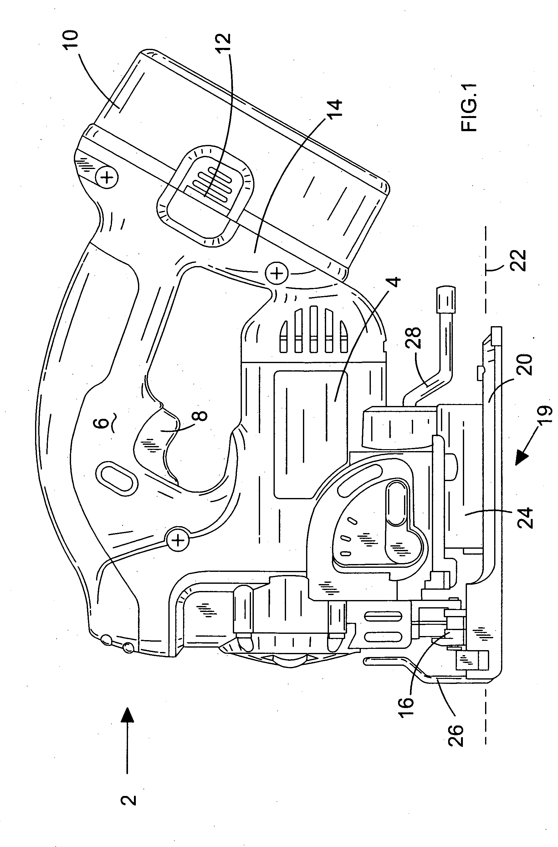
[0025] Referring to FIG. 1, a jigsaw 2 comprises a housing 4 formed from moulded plastics material in two clamshell halves (not shown) as will be familiar to persons skilled in the art. A handle 6 is integrally formed with the housing 4 to allow a user to grip the jigsaw 2 and depress switch 8 to activate a motor (not shown) of the jigsaw 2. A removable and rechargeable battery pack 10 is shown mounted to the housing 4. The battery pack 10 is removed from the housing 4 by depressing resilient clips 12, and the action of pushing the battery pack 10 back into rear portion 14 of the housing 4 displaces resilient clips 12 such that the battery pack 10 locks in place on the rear of housing 4.

[0026] A blade clamp 16 releasably holds a jigsaw blade (not shown), and executes reciprocating vertical movement when the jigsaw motor is activated. The blades may be of the standard type, or of the flush-cut type as shown in FIG. 4 and which extend further forwards than standard blades, for exampl...


PUM

PropertyMeasurementUnit
Angleaaaaaaaaaa

Abstract

A shoe assembly for a power tool comprises a shoe portion including a cast and a sole plate adapted to engage a workpiece. The cast has a raised portion having a series of recesses on an interior surface thereof. The shoe assembly also includes a mounting portion for mounting the shoe portion to the housing of the tool. The mounting portion includes a resiliently displaceable ball bearing in a housing mounted to a clamp plate for engaging the recess on the raised portion of the cast in order to selectively releasably hold the shoe portion in one of a plurality of predetermined orientations relative to the mounting portion.

Description

FIELD OF THE INVENTION [0001] The present invention relates to a shoe assembly for a power tool and relates particularly, but not exclusively, to a shoe assembly for a jigsaw. The invention also relates to power tools incorporating such assemblies. BACKGROUND OF THE INVENTION [0002] Jigsaws are power tools housing a motor for reciprocatingly driving a blade. The housing generally rests on a shoe assembly for supporting the saw on a workpiece, and the blade projects through the shoe in order to cut the workpiece. Jigsaws can also be equipped to perform bevel cutting, in which the blade is tilted about the longitudinal axis of the shoe in order to produce angular cuts in the workpiece. [0003] Bevel cutting jigsaws are known which have preset angular inclinations, and mechanisms for locking the blade at an angle to the workpiece. U.S. Pat. No. 6,357,124 describes a clamping mechanism for a bevel-cutting jigsaw in which deflectable ball bearings are held on the underside of a housing of...

Claims


Application Information

Patent Timeline
IPC IPC(8): B23D49/16B23D51/02B27B3/12F16D51/00
CPCB23D51/02B23D49/167
Inventor WALMSLEY, NEIL
Owner BLACK & DECKER INC
Learn More