Seismic-protection wheel locational anchorage

a technology of seismic protection and location anchorage, which is applied in the direction of shock resistance, brake system, manufacturing tools, etc., can solve the problems of increased working cost, insufficient strength of seismic protection anchorage feet, and failure to position seismic protection fastening elements at the leveling

Inactive Publication Date: 2005-12-29
IND TECH RES INST
View PDF8 Cites 25 Cited by
  • Summary
  • Abstract
  • Description
  • Claims
  • Application Information

AI Technical Summary

Benefits of technology

[0007] The objective of the present invention is to provide a seismic-protection wheel locational anchorage including a first fastening member and a second fastening member capable of separately joining together. The first fastening member is fastened to a bottom of a machine frame by a fastening means passing through an elongated hole on the first fastening member and one locating hole on the machine frame originally had for a wheel, and the second fastening member is securely fastened to the ground by another fastening means. The joint location between the first fastening member and the second fastening member is adjustable so as to fit the vertical gap between the machine and the ground. The machine can be firmly fastened to the ground by the present seismic-protection wheel locational anchorage. Extra work to drill additional holes on the machine frame used for fastening is avoided.
[0011] The first fastening member and the second fastening member can be joined together by a check bolt with a spring washer passing through the second elongated hole and the fourth elongated hole. The joining between the first fastening member and the second fastening member is thus reinforced.

Problems solved by technology

However, the strength of these leveling feet cannot sufficiently resist the transverse force produced by an earthquake.
Although it is convenient to position the seismic-protection fastening brackets at the leveling feet, the insufficient strength of the leveling feet and the association between the seismic-protection fastening brackets and the leveling feet would result in a failure for positioning the seismic-protection fastening elements at the leveling feet.
Moreover, if the manufacturing equipment is not provided with receiving places for the seismic-protection fastening kits when manufactured, it will be necessary to drill holes on the manufacturing equipment for positioning the seismic-protection fastening elements.
As a consequence, the working cost is increased.
If the manufacturing equipment is larger and heavier, it is necessary to install several wheels on when the manufacturing equipment is to be transported.

Method used


Image

  • Seismic-protection wheel locational anchorage
  • Seismic-protection wheel locational anchorage
  • Seismic-protection wheel locational anchorage

Examples


first embodiment

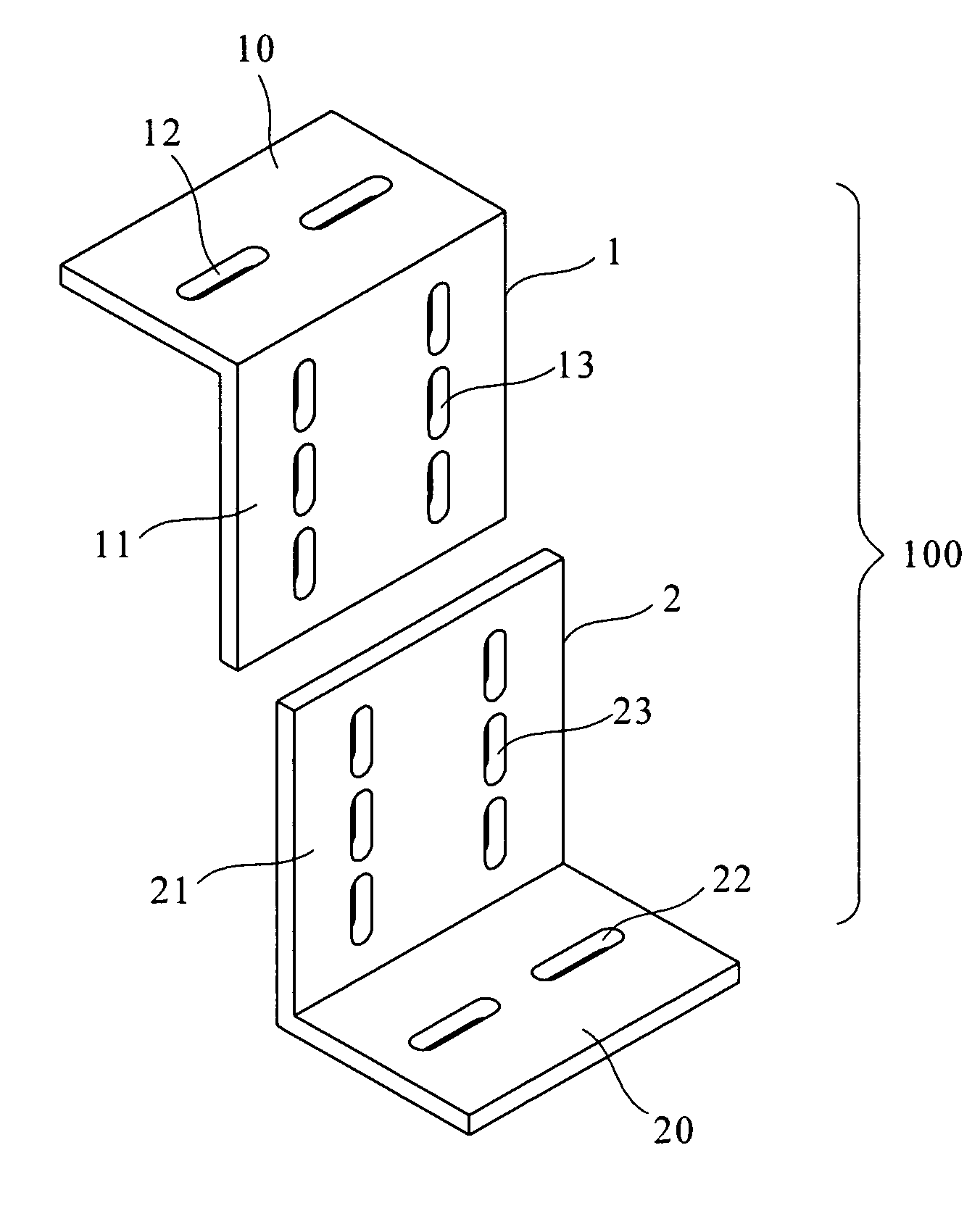
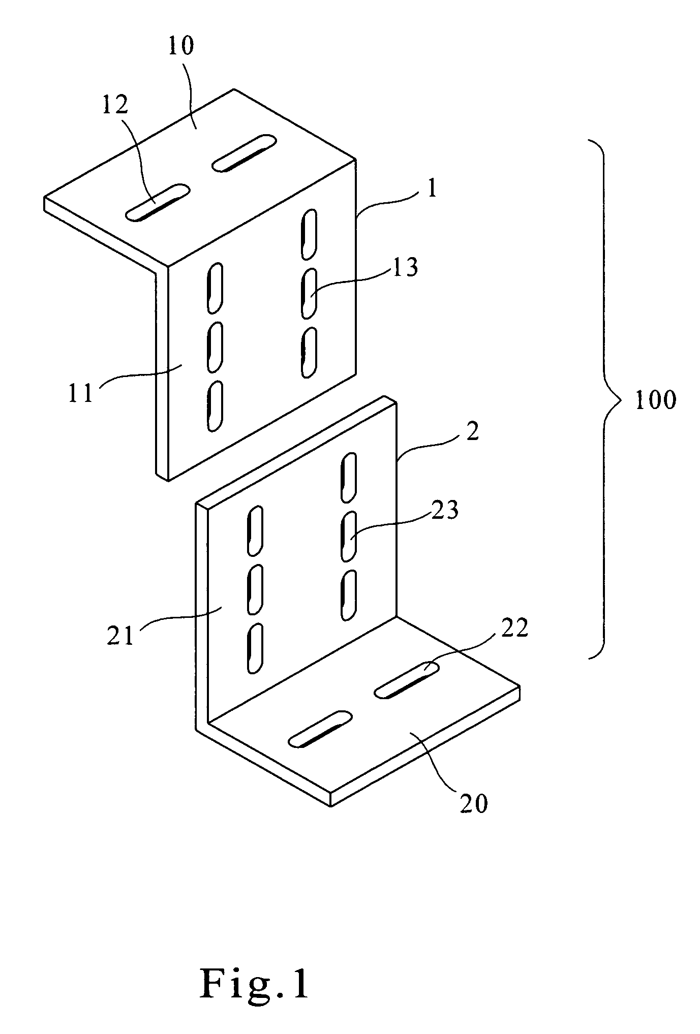
[0025]FIG. 1 is a schematic exploded view of a seismic-protection locational anchorage according to the present invention. The seismic-protection locational anchorage 100 includes: a first fastening member 1 having a first horizontal part 10 and a first perpendicular part 11 vertically and downwardly extending from one end of the first horizontal part 10, the first horizontal part 10 is provided with a pair of first elongated holes 12 and the first perpendicular part 11 is provided with three pairs of second elongated holes 13; and a second fastening member 2 having a second perpendicular part 21 and a second horizontal part 20 extending parallel from a lower end of the second perpendicular part 21, the second horizontal part 20 is provided with a pair of third elongated holes 22 and the second perpendicular part 21 is provided with three pairs of fourth elongated holes 23.

[0026] The first elongated holes 12 are formed on the first horizontal part 10 of the first fastening member 1 ...

second embodiment

[0028]FIG. 3 and FIG. 4 respectively are schematic exploded view and assembled view of the seismic-protection locational anchorage 100 according to the present invention. The seismic-protection locational anchorage 100 includes: a first fastening member 1 having a first horizontal part 10 and a first perpendicular part 11 vertically and downwardly extending from one end of the first horizontal part 10, the first horizontal part 10 is provided with a pair of first elongated holes 12 and the first perpendicular part 11 is provided with a pair of second elongated holes 13 and a pair of first inclined elongated holes 14; and a second fastening member 2 having a second perpendicular part 21 and a second horizontal part 20 extending parallel from the lower end of the second perpendicular part 21, the second horizontal part 20 is provided with a pair of third elongated holes 22 and the second perpendicular part 21 is provided with a pair of fourth elongated holes 23 and a pair of second in...


PUM


Abstract

A seismic-protection wheel locational anchorage is provided. The present seismic-protection wheel locational anchorage includes a first fastening member and a second fastening member. The first fastening member has a first horizontal part and a first perpendicular part vertically and downwardly extending from one end of the first horizontal part. The second fastening member has a second perpendicular part and a second horizontal part extending parallel from a lower end of the second perpendicular part. The first horizontal part of the first fastening member is fastened to the bottom of a machine frame. The second horizontal part is securely fastened to the ground. When the vertical level between the machine frame and the ground is appropriately adjusted, the first perpendicular part and the second perpendicular part are securely joined together so as to provide the seismic-protection wheel locational anchorage for the machine frame.

Description

BACKGROUND OF THE INVENTION [0001] 1. Field of the Invention [0002] The present invention relates to a seismic-protection fastening means, and more particularly to a seismic-protection wheel locational anchorage, by which a machine can be securely fastened to the ground. [0003] 2. Description of the Related Art [0004] Taiwan is located in a fault-concentrated zone, about two hundred felt earthquakes occur in Taiwan every year. Thus, seismic-protection for manufacturing equipment is required as most components are very precise in essentiality and in function. In addition to seismic-protection fastening elements provided in the manufacturing equipment, for convenient operation and easy installation, brackets on leveling feet are provided for the most manufacturing equipments to serve as fastening elements. These seismic-protection elements are positioned at the feet of the stand. [0005] However, the strength of these leveling feet cannot sufficiently resist the transverse force produc...

Claims


Application Information

Patent Timeline
Patent Type & Authority Applications(United States)
IPC IPC(8): B23Q1/00B60T3/00E04B1/98F16M5/00F16M7/00
CPCF16M7/00E04B2001/405E04B2001/389
Inventor CHEN, YING-JIE
Owner IND TECH RES INST
Why Eureka
Try Eureka