Method of sensor conditioning for improving signal output stability for mixed gas measurements

a technology of mixed gas and signal output stability, applied in the field of gas sensors, can solve the problems of reducing the sensor output, not allowing the development of a viable commercial sensor, and inversely proportional to the generated curren

Active Publication Date: 2005-12-29
BJR SENSORS
View PDF13 Cites 49 Cited by
  • Summary
  • Abstract
  • Description
  • Claims
  • Application Information

AI Technical Summary

Problems solved by technology

On the other hand, reduction reaction (3) will increase the oxygen ions concentration in the vicinity of TPBL, thus the presence of increased concentrations of nitrogen monoxide will decrease the sensor output.
These sensors clearly demonstrated strong response to the presence of carbon monoxide and nitrogen oxide; however, their lack of stability, repeatability and selectivity did not allow the development of a viable commercial sensor.
The drawback of DPV is related to the fact that the generated current is inversely proportional to the sensor electrode resistance.

Method used


Image

  • Method of sensor conditioning for improving signal output stability for mixed gas measurements
  • Method of sensor conditioning for improving signal output stability for mixed gas measurements
  • Method of sensor conditioning for improving signal output stability for mixed gas measurements

Examples


example 1

1. EXAMPLE 1

Nitrogen Oxide (NO) Measurements

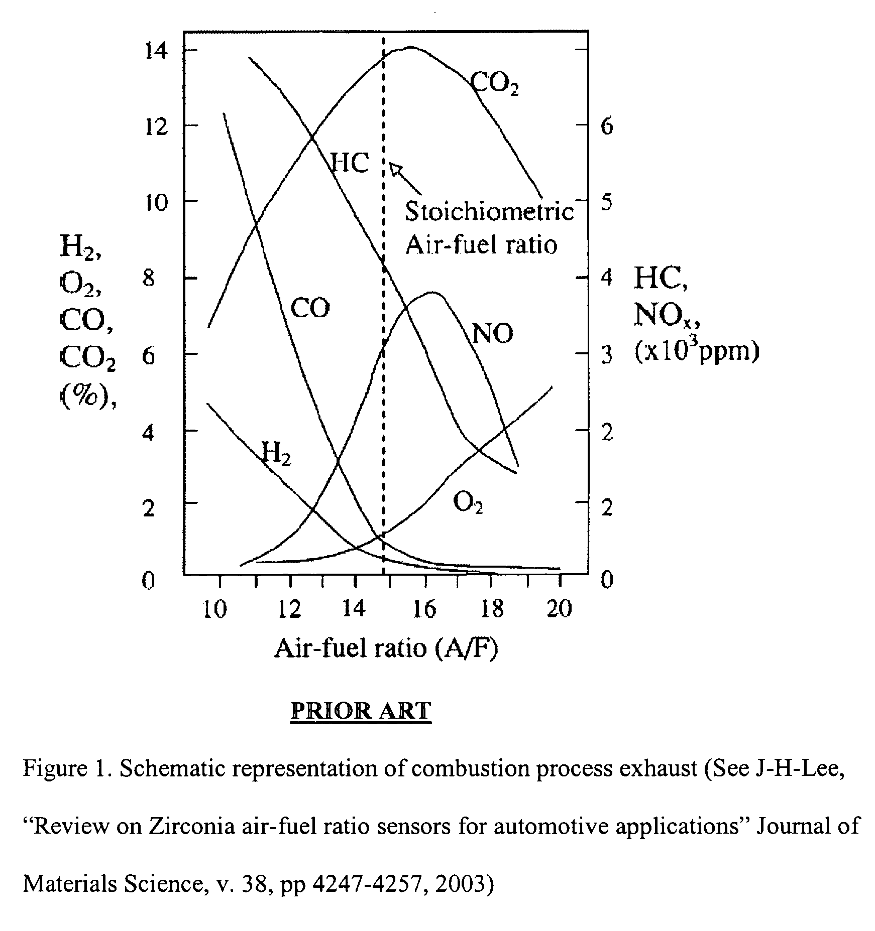
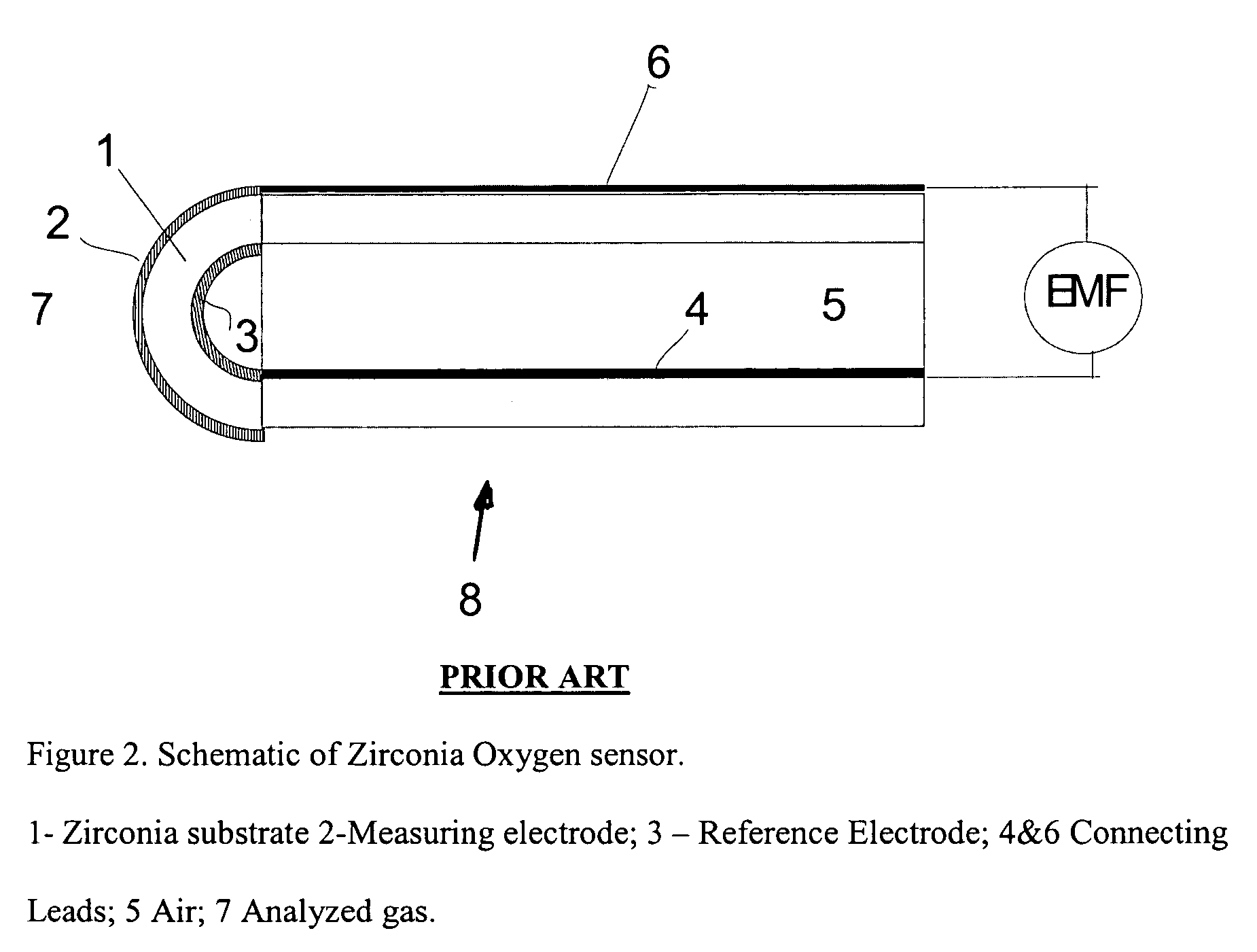
[0050] According to one example of the preferred embodiment of the present invention a concentration of NO was measured by using a traditional zirconia oxygen sensor and the proposed conditioning treatment. An Exhaust Gas Oxygen sensor (EGO) (capable of accurate measurements of oxygen concentrations in a wide range 0.5-10%) was placed inside a heated furnace with the temperature of ˜510° C. The sensor was equipped with an internal heater and the heater voltage was set at V=10 Volts. The sensor measurement electrode was exposed to different mixtures of N2; O2; NO; NO2, and CO gases, simulating conditions in the combustion process exhaust.

[0051] To demonstrate advantages of the proposed method, we first exposed sensor to pulse changes in the concentration of NO (0-1000 ppm) at O2 concentration of 3% (balance N2). FIG. 8 shows the EGO sensor mV response to applied NO. Sensor response is rather weak (<15 mV) and shows significant drift of th...

example 2

Measurements of CO

[0060] Sensitivity to different gases in the exhaust gas mixture can be varied in the preferred embodiment of the present invention by varying amplitude of the conditioning voltage pulses. FIG. 20 shows sensor response to 1500 ppm CO (at 2% O2) while subjecting sensor to conditioning treatment with the amplitude of conditioning voltage pulses=1 Volts. Sensor sensitivity to CO has significantly improved as compared with the conditioning treatment with the voltage amplitude of 2.5 Volts

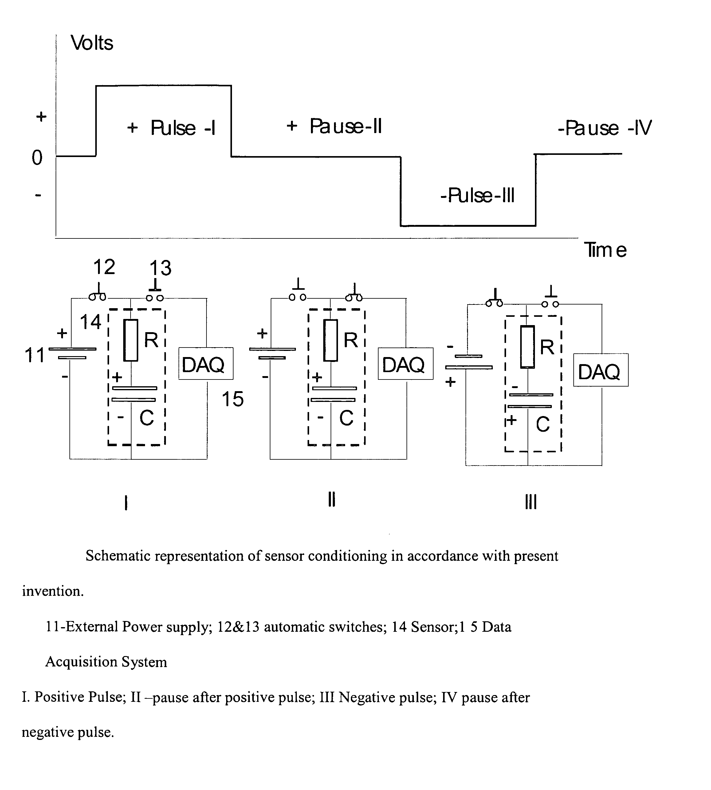
[0061] An alternative method of CO / NOx detection can be based on measuring the charge / discharge current during pulses and pauses. FIG. 21 shows a diagram of these measurements. Sensor (14) is represented by resistor R and capacitor C connected in series. During a positive Pulse (I), the sensor is connected with the power supply (11) by closing the switch (12) and opening switch (13). The measuring sensor electrode (exposed to analyzed gas) is charged positively according to the polar...


PUM

PropertyMeasurementUnit
temperatureaaaaaaaaaa
voltage amplitudeaaaaaaaaaa
polarityaaaaaaaaaa

Abstract

A method of sensor conditioning is proposed for improving signal output stability and differentiation between responses to different gases such as exhaust from combustion processes. A square wave (or saw tooth) voltage pulses of opposite polarity and equivalent amplitude are applied between sensor electrodes. Pulses are separated by pauses, when charging power supply is disconnected from the sensor and sensor discharge is recorded. Useful information regarding concentration of analyzed gases can be extracted from two measurement methods: 1. Measuring open circuit voltage decay during the pause immediately following voltage pulse. 2. Measuring the charging current during positive (negative) pulses and the discharging current during pauses following voltage pulses.

Description

RELATED APPLICATIONS [0001] The present invention claims the benefit of U.S. Provisional Patent No. 60 / 580,606, filed on Jun. 18, 2004 and U.S. Provisional Patent No. 60 / 599,513, filed on Aug. 9, 2004, both of which are incorporated by reference as if fully rewritten herein.BACKGROUND OF THE INVENTION [0002] 1. Field of the Invention [0003] The present invention relates generally to gas sensors and more particularly to mixed-potential gas sensors for detecting gases such as carbon monoxide, unburned hydrocarbons and nitrogen oxide, which are common in combustion exhaust. [0004] 2. Description of the Related Art [0005] Combustion exhaust gases contain the following major components, namely N2, O2, CO, CO2, H2O, and NOx. In the fuel rich region, exhaust contains excessive concentrations of CO and hydrocarbons (HC). In the fuel lean region, exhaust contains excessive concentration of NOx. Close to the stoichiometric point, exhaust contains minimal concentration of these harmful contami...

Claims


Application Information

Patent Timeline
Patent Type & Authority Applications(United States)
IPC IPC(8): G01N27/26G01N27/406
CPCG01N27/4065
Inventor FARBER, BORIS
Owner BJR SENSORS
Why Eureka
Try Eureka