Protective wrap for microwavable container
a protective wrap and container technology, applied in the field of paperboard wrap for a microwavable container, can solve the problems of inadvertent drop of the container, high temperature of the external surface of the container, and other undesirable consequences
- Summary
- Abstract
- Description
- Claims
- Application Information
AI Technical Summary
Benefits of technology
Problems solved by technology
Method used
Image

Examples
first embodiment
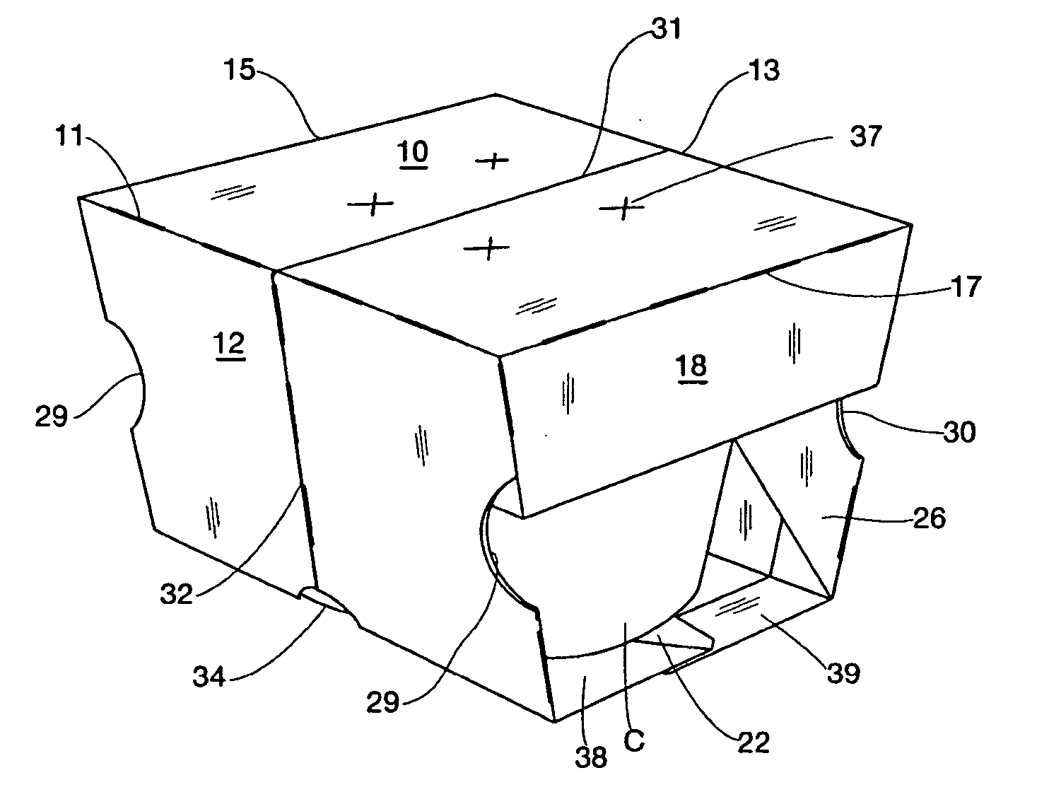
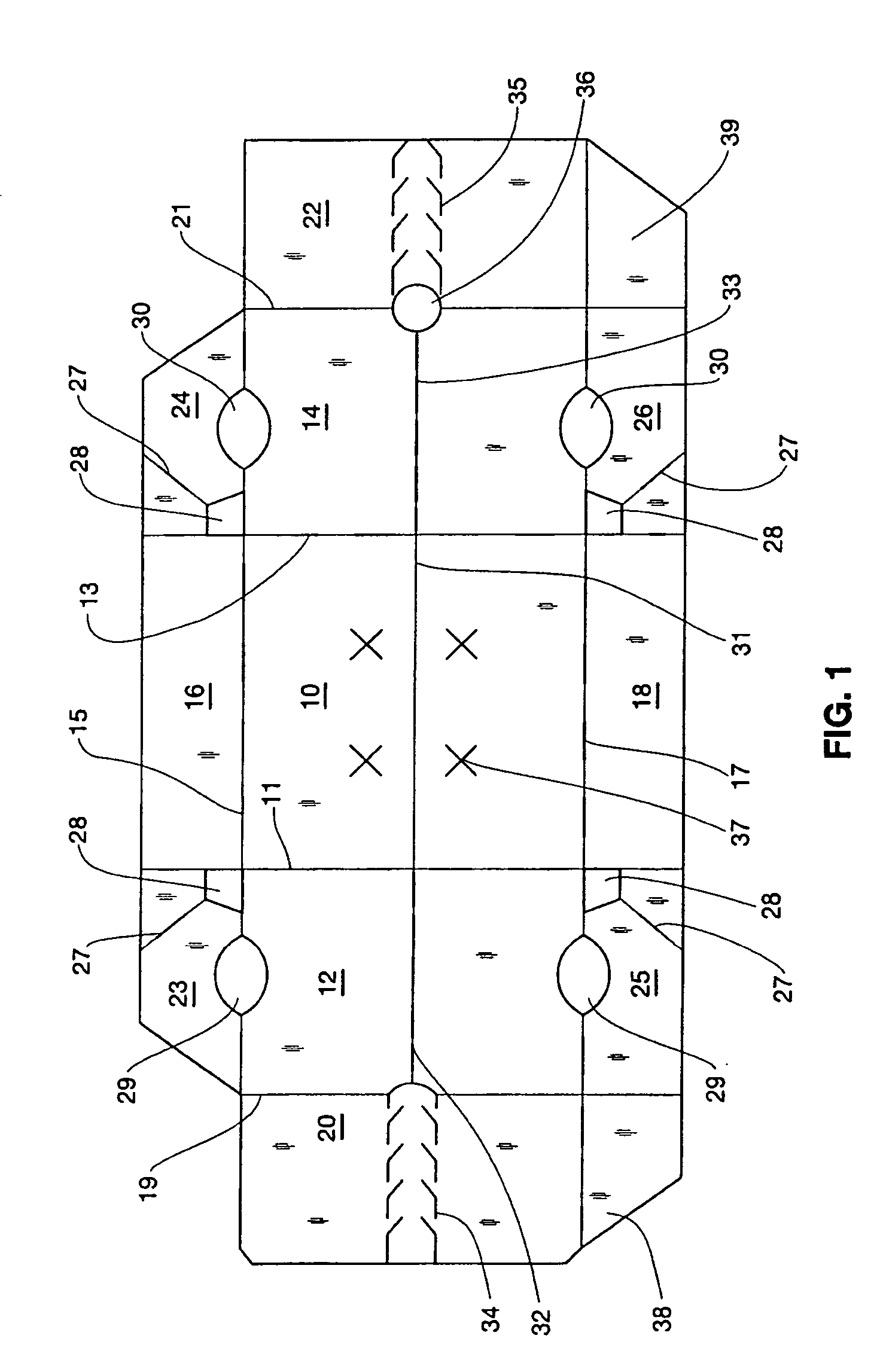
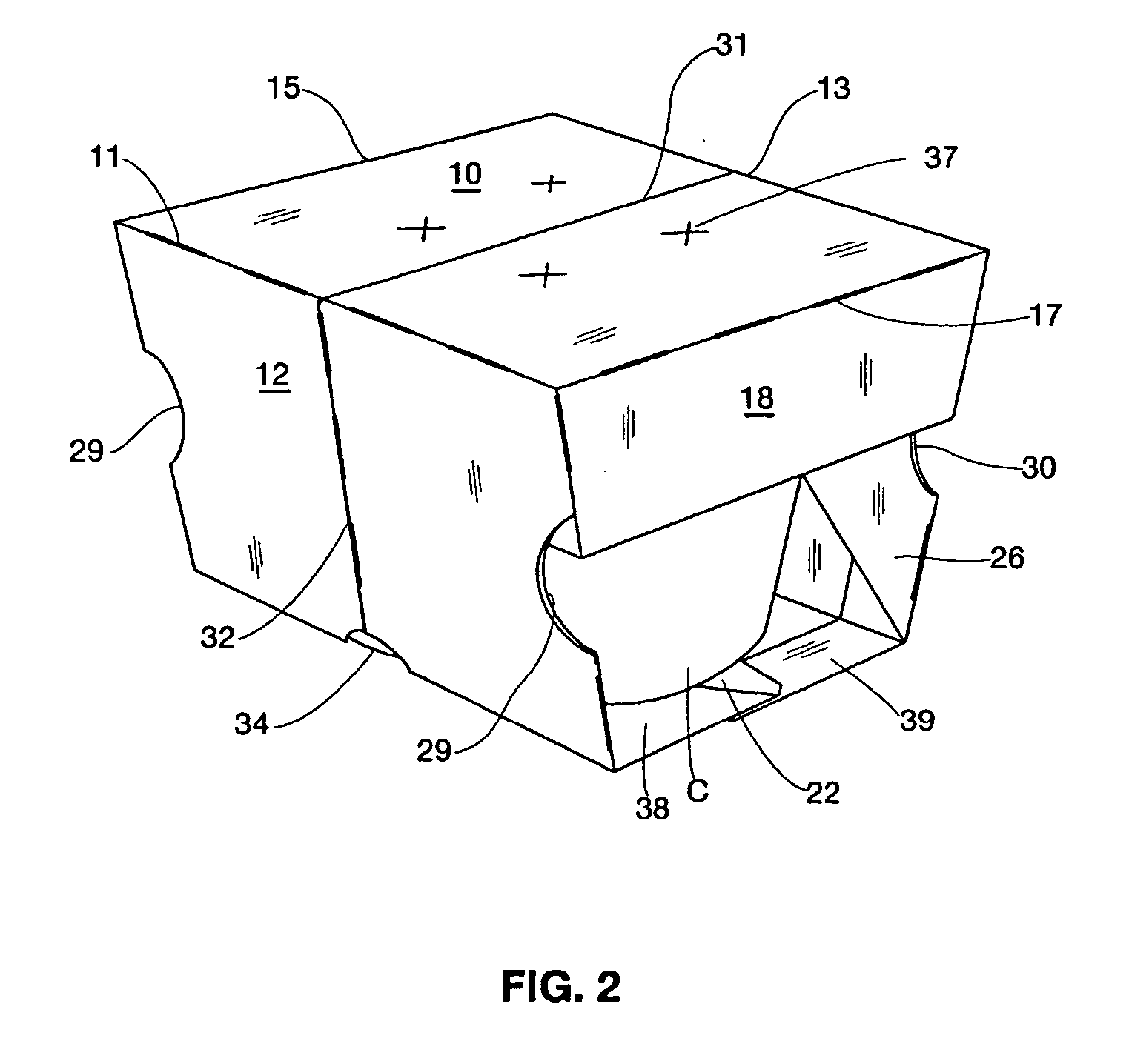
[0019] the wrap of the invention is formed from a blank made of a foldable sheet of material, such as paperboard. The blank, shown in FIG. 1, has a top wall 10, which is joined by fold line 11 to side wall 12, by fold line 13 to side wall 14, by fold line 15 to side wall 16, and by fold line 17 to side wall 18. Side wall 12 is joined by fold line 19 to bottom flap 20, and side wall 14 is joined by fold line 21 to bottom flap 22.
[0020] As shown in FIG. 1, in the blank for forming the first embodiment of the wrap of the invention, side wall 16 has a gusset 23, 24 at each end. Gusset 23 is joined to side wall 16 by fold line 11, and to side wall 12 by fold line 15, and gusset 24 is joined to side wall 16 by fold line 13, and to side wall 14 by fold line 13. Gussets 23, 24 taper down at their outside edges to meet the ends of fold lines 19, 21 respectively. Side wall 18 has a gusset 25, 26 at each end, gusset 25 being joined to side wall 18 by fold line 11 and to side wall 12 by fold li...
second embodiment
[0028] the wrap of the invention is formed from the blank shown in FIG. 6. This blank has a top wall 110 which is joined by fold line 111 to side wall 112, by fold line 113 to side wall 114, by fold line 115 to side wall 116, and by fold line 117 to side wall 118. Side wall 112 is joined by fold line 119 to bottom flap 120, and side wall 114 is joined by fold line 121 to bottom flap 122.
[0029] As shown in FIG. 6, in the blank for forming the second embodiment of the wrap of the invention, side wall 116 has a gusset 123, 124 at each end, gusset 123 being joined to side wall 116 by fold line 111, and to side wall 112 by fold line 115, and gusset 124 being joined to side wall 116 by fold line 113, and to side wall 114 by fold line 113. Side wall 118 has a gusset 125, 126 at each end, gusset 125 being joined to side wall 118 by fold line 111 and to side wall 112 by fold line 117, and gusset 126 being joined to side wall 118 by fold line 113, and to side wall 114 by fold line 117. Gusset...
third embodiment
[0036] the wrap of the invention is formed from the blank shown in FIG. 10. This blank is basically the same as the blank shown in FIG. 6, except for the location of the hinge line and tear lines.
[0037] In the blank of FIG. 10, the hinge line 231 is located in top wall adjacent and parallel to fold line 215, and extends between fold lines 211 and 213. From the junction of hinge line 231 and fold line 211, a tear line 232 extends across side wall 212, away from fold line 211, and then parallel to it and across gusset 225 to the outer edge of the blank. Likewise, tear line 233 extends from the junction of hinge line 231 and fold line 213 across side wall 214, away from fold line 213, and then parallel to it and across gusset 226 to the outer edge of the blank. Preferably, the distance between tear line 232 and fold line 211, the distance between tear line 233 and fold line 213, and the width of side wall 218 between fold line 217 and outer edge of the blank, are all approximately equa...
PUM
 Abstract
Description
Claims
Application Information
 - Generate Ideas
- Intellectual Property
- Life Sciences
- Materials
- Tech Scout
- Unparalleled Data Quality
- Higher Quality Content
- 60% Fewer Hallucinations
Browse by: Latest US Patents, China's latest patents, Technical Efficacy Thesaurus, Application Domain, Technology Topic, Popular Technical Reports.
© 2025 PatSnap. All rights reserved.Legal|Privacy policy|Modern Slavery Act Transparency Statement|Sitemap|About US| Contact US: help@patsnap.com