Method for operating a belt retractor and a belt retractor for a safety belt

a technology of belt retractor and safety belt, which is applied in the direction of belt retractor, vehicle safety belt, belt retraction, etc., can solve the problem that the force-limiter system of the safety belt is not substantially increased

Inactive Publication Date: 2005-12-29
TRW AUTOMOTIVE GMBH
View PDF7 Cites 12 Cited by
  • Summary
  • Abstract
  • Description
  • Claims
  • Application Information

AI Technical Summary

Benefits of technology

[0007] In order to solve this problem, the invention provides a method in which, when the belt tensioner drive is activated, through the activation of the belt tensioner drive the pre-tensioner drive is prevented from exerting a torque on the belt spool. A belt retractor according to the invention is distinguished in that a safety mechanism is provided, which with an activation of the belt tensioner drive prevents the pre-tensioner drive from driving the belt spool in the w

Problems solved by technology

Then only the electric motor has to be carried along; the torque occurring here is, however, comparatively sm

Method used


Image

  • Method for operating a belt retractor and a belt retractor for a safety belt
  • Method for operating a belt retractor and a belt retractor for a safety belt
  • Method for operating a belt retractor and a belt retractor for a safety belt

Examples


second embodiment

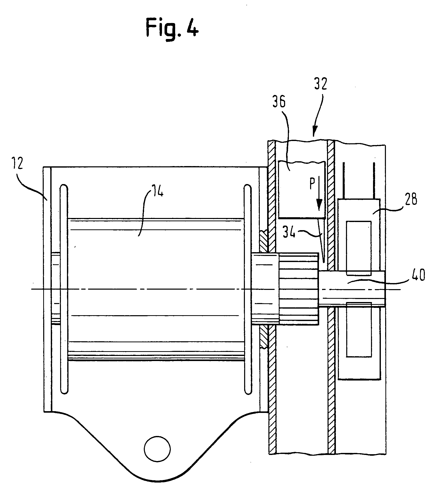
[0032] In FIG. 4 a second embodiment is shown. The safety mechanism 32 also has an actor 36 here, which can move a separating element 34. In the same manner as in the embodiment according to FIGS. 2 and 3, the separating element is constructed as a sharp blade. This blade acts here on a shaft 40 which connects the pre-tensioner drive 28 with the belt spool 14. Through activation of the pyrotechnic gas generator 26, the actor 36 moves the separating element 34 in the direction of the arrow P, whereby the shaft 40 is separated, sheared off or otherwise broken. Provision can be made that the shaft 40 is provided with a nominal fracture site.

third embodiment

[0033] In FIG. 5 a third embodiment is shown. Instead of the shaft 40, here a connecting pin 42 leads between the pre-tensioner drive 28 (symbolized here by a pinion) and the belt tensioner drive 24 (symbolized here by a pinion coupled with the belt spool 14). The connecting pin can be transferred by the actor 36 (formed here by a pressure chamber which is closed of from one end side of the connecting pin 42 and can be acted upon by the pressure of the compressed gas generated by the gas generator 26) in the direction of the arrow from the initial position shown in FIG. 5, in which the pre-tensioner drive 28 is coupled with the belt spool 14, into a separating position in which the connecting pin 42 no longer engages into the pinion of the belt tensioner drive 24 and thereby the connection to the belt spool 14 is interrupted.

fourth embodiment

[0034] In FIGS. 6 and 7 a fourth embodiment is shown. Here, also, a connecting pin 42 is used, which can be transferred from an initial position (see FIG. 6) into a separating position (see FIG. 7). In the initial position, the connecting pin 42 connects two toothed wheels 50, 52 which are part of a gear 54 between the electric motor 30 of the pre-tensioner drive and the belt spool 14. In the initial state, the connecting pin 42 provides a torque-transferring connection between the two toothed wheels 50, 52. At the same time, it serves for mounting. A slider 56 engages on the connecting pin 42, which slider can be acted upon by the actor 36 so that it draws the connecting pin 7 in the direction of the arrow P into the separating position. In the latter, the torque-transferring connection between the two toothed wheels 50, 52 is interrupted, so that the belt spool can turn in the unwinding direction without the electric motor 30 having to be entrained.

[0035] According to a further de...


PUM


Abstract

In a method for operating a belt retractor, the belt retractor comprising a belt tensioner drive and with a pre-tensioner drive which can both exert a torque onto a belt spool in a direction for winding a safety belt, the pre-tensioner drive is prevented from exerting a torque onto the belt spool through the activation of the belt tensioner drive. In a belt retractor for a safety belt, having a belt spool, a pre-tensioner drive with a drive motor, which can turn the belt spool in the winding direction for the purpose of pre-tensioning the safety belt, and with a belt tensioner drive which can drive the belt spool for the purpose of a belt tensioning, a safety mechanism is provided, which through an activation of the belt tensioner drive prevents the pre-tensioner drive from driving the belt spool in the winding direction.

Description

[0001] The invention relates to a method for operating a belt retractor. BACKGROUND OF THE INVENTION [0002] The invention in particular relates to a belt retractor which is provided with a belt tensioner drive and with a pre-tensioner drive, which can both exert a torque onto a belt spool in a direction for winding the safety belt. The invention additionally relates to a belt retractor for a safety belt, with a belt spool, a pre-tensioner drive with a drive motor which can rotate the belt spool for the purpose of pre-tensioning the safety belt in the winding direction, and with a belt tensioner drive which can drive the belt spool for the purpose of a belt tensioning. [0003] Both the pre-tensioner drive and also the belt tensioner drive basically serve to drive the belt spool in the winding direction when a vehicle state exists which is classified as critical, so that the so-called belt slack of the safety belt is eliminated and the safety belt lies taut against the body of a vehicl...

Claims


Application Information

Patent Timeline
IPC IPC(8): B60R22/46B65H75/48
CPCB60R22/4628B60R2022/468B60R2022/4666B60R22/4676
Inventor HOLBEIN, WOLFGANGPROKSCHA, MARTIN
Owner TRW AUTOMOTIVE GMBH
Why Eureka
Try Eureka