Scanning mechanism of an ion implanter

a scanning mechanism and implanter technology, applied in the field of implanters, can solve the problems of increasing power consumption, exacerbating the error in angle control and scan control of wafers, etc., and achieve the effect of reducing the load of the scanning mechanism and reducing the power consumption of the motor installed

Active Publication Date: 2005-12-29
TSINGHUA UNIV
View PDF9 Cites 11 Cited by
  • Summary
  • Abstract
  • Description
  • Claims
  • Application Information

AI Technical Summary

Benefits of technology

[0005] An object of the invention is to provide a mechanism for controlling the implant angle and scan motion of a wafer holder in an ion implanter with two parallel subchains, to...

Problems solved by technology

The weight of motor 1, which is relatively large and increases the load of the scanning mechanism, leads to rise in the power consumption of motor 2 ...

Method used


Image

  • Scanning mechanism of an ion implanter
  • Scanning mechanism of an ion implanter
  • Scanning mechanism of an ion implanter

Examples


Embodiment Construction

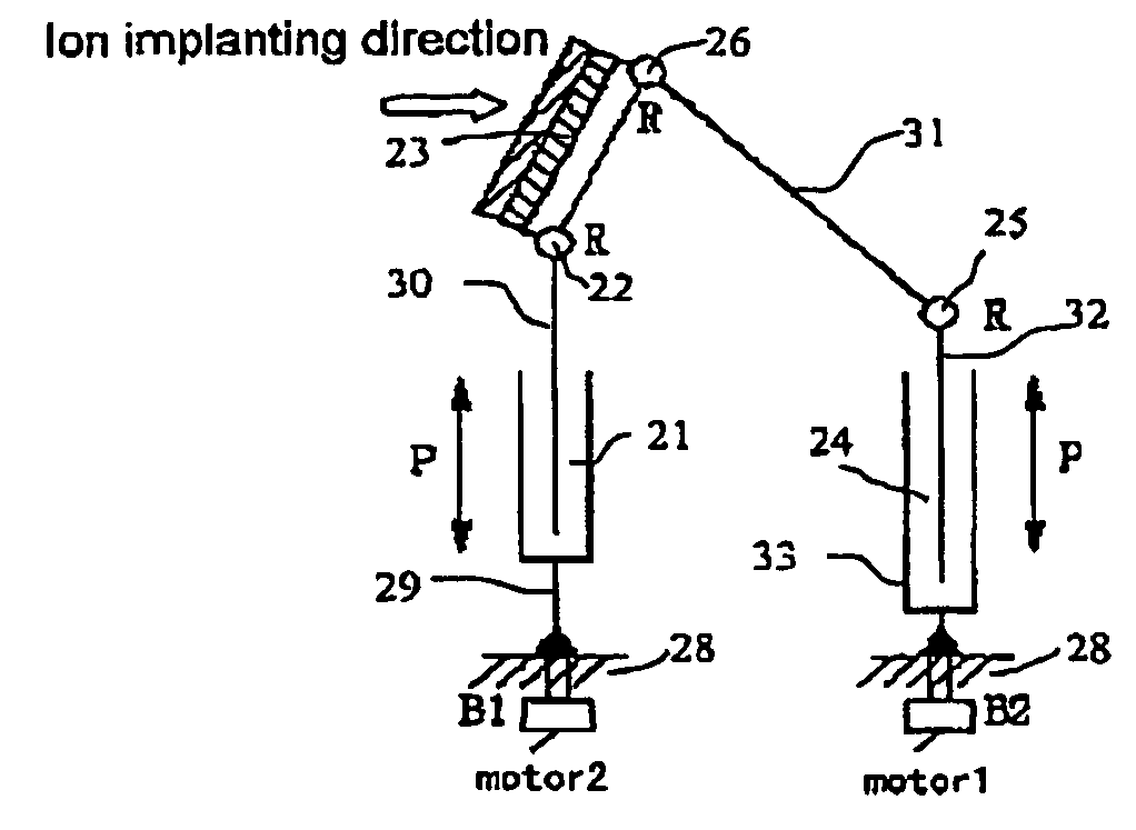
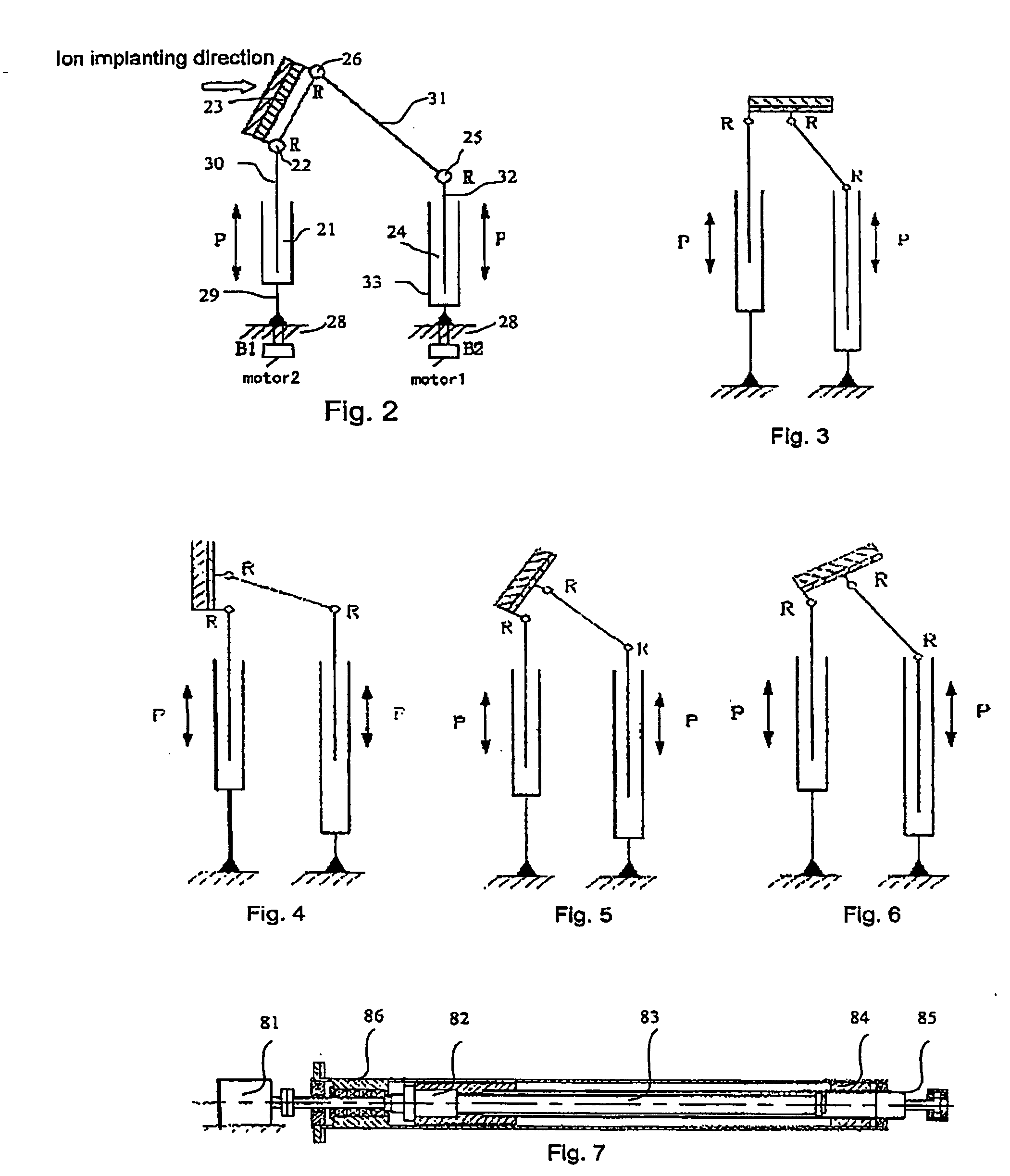
[0023] The present invention uses a 2-DOF (degree-of-freedom) parallel mechanism with two subchains to control rotational angle adjustment and scan of a wafer holder. In the so-called parallel mechanism, there are two subchains from the wafer holder to the wall of the chamber of the ion implanter where the 2-DOF parallel mechanism is fixed. FIG. 2 shows an example of the mechanism.

[0024] In the 2-DOF parallel mechanism with two subchains according to the invention, the first subchain takes the form of PR-type, i.e. it comprises a first prismatic pair 21 and a first revolute pair 22. The first prismatic pair 21 comprises a first fixing link 29 and a first moving link 30. Being driven by a motor, the first moving link 30 can move repeatedly with respect to the first fixing link 29 in its longitudinal axial direction, i.e. the direction as indicated by the double arrow P in the figure. The first fixing link is fixed rigidly to chamber wall 28 of the ion implanter and the first moving ...


PUM


Abstract

This invention discloses a scanning mechanism of an ion implanter. The mechanism is a PR-PRR type parallel mechanism with two subchains and two DOFs, driving the wafer holder to scan when the first subchain and the second subchain are translated in the same direction at the same speed and adjusting the rotational angle of the wafer holder when the first moving link (30) and the second moving link (32) in the first subchain and the second subchain have different translation amounts in the same direction or opposite directions. The driving motor for the scanning mechanism is provided outside the implant chamber. The invention also solves problems like low rigidity and large accumulation errors of existing serial scanning mechanisms and the effect of the electromagnetic field of the motor within the ion implant chamber on the trajectory of the ion beam.

Description

FIELD OF THE INVENTION [0001] The invention relates to an ion implanter, and more particularly, to a scanning mechanism of an ion implanter. BACKGROUND OF THE INVENTION [0002] Ion implanters are applied widely in manufacturing semiconductor wafers. Before an ion beam is implanted, the angle between the normal axis of the surface of wafer 416 and the direction of the ion beam 404 (as shown in FIG. 1), named implant angle, is adjusted to a desired value. The wafer 416 is fixed on the wafer holder 414. When the ion beam is implanted, the wafer holder 414 is then driven to bring the wafer to perform repeatedly translational scan perpendicular to the direction of ion beam implantation, while maintaining implant angle unvaried. To ensure the dose of ion implantation over he wafer to be uniform, it's necessary to precisely control the implant angle and the scanning motion of the wafer holder 416. [0003] In conventional ion implanters as shown in FIG. 1, a scanning mechanism with a wafer ho...

Claims


Application Information

Patent Timeline
IPC IPC(8): A61N5/00G21K5/10H01J37/317H01L21/00H01L21/265H01L21/68H01L21/687
CPCH01J2237/20207H01J2237/20228H01J2237/20278H01L21/68764H01L21/67213H01L21/68H01J2237/31701
Inventor WANG, JINSONGZHU, YUCAO, JIANYONGYIN, WENSHENGDUAN, GUANGHONG
Owner TSINGHUA UNIV
Why Eureka
Try Eureka