Bicycle rear suspension system

a rear suspension and bicycle technology, applied in the field of bicycles, can solve problems such as relative complexity in structure, and achieve the effect of simple structur

Active Publication Date: 2005-12-29
GIANT MFG
View PDF19 Cites 47 Cited by
  • Summary
  • Abstract
  • Description
  • Claims
  • Application Information

AI Technical Summary

Benefits of technology

[0005] The object of this invention is to provide a bic

Problems solved by technology

Although the bicycle rear suspension system can effectively absorb sho

Method used


Image

  • Bicycle rear suspension system
  • Bicycle rear suspension system
  • Bicycle rear suspension system

Examples


Embodiment Construction

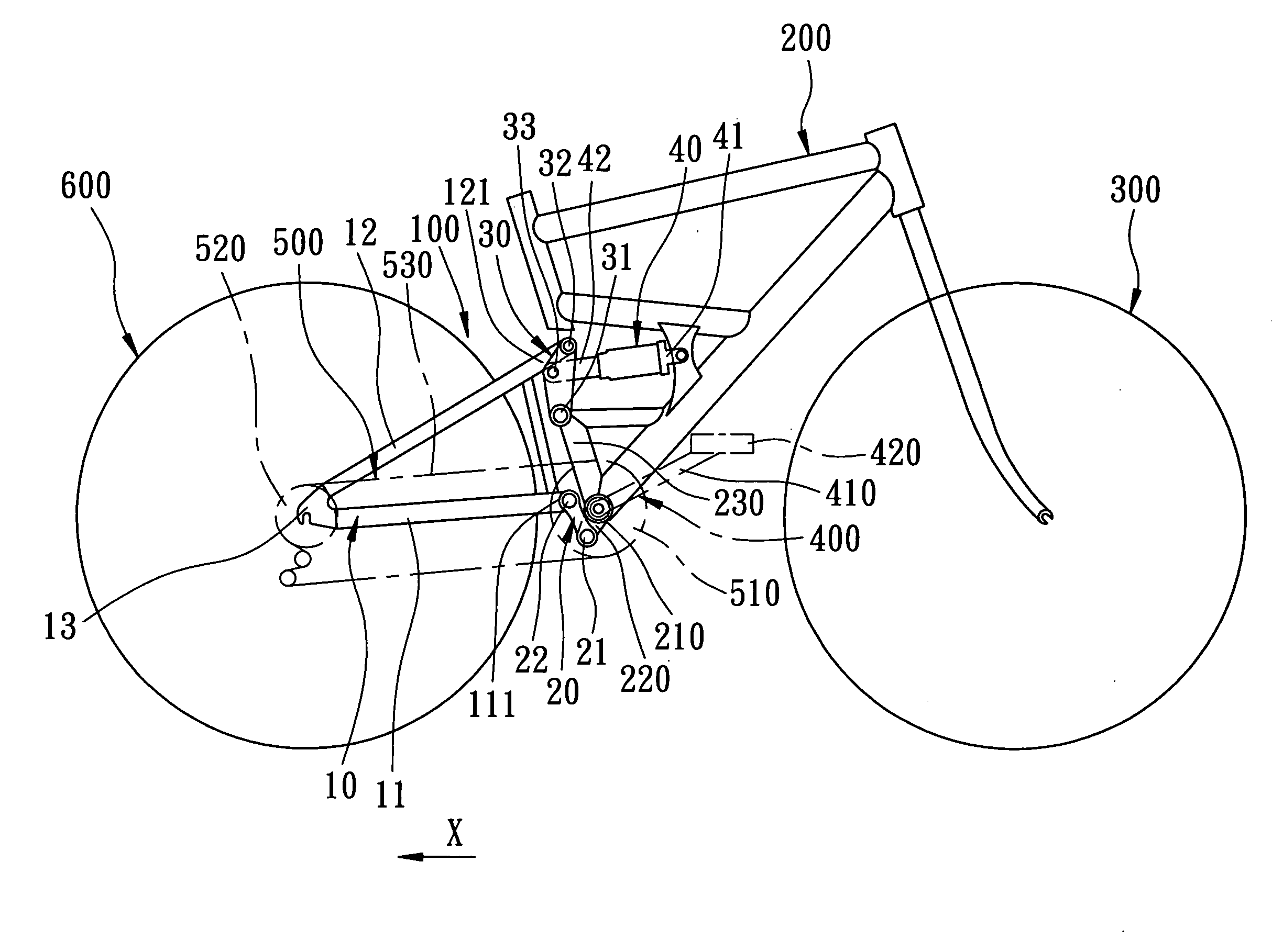
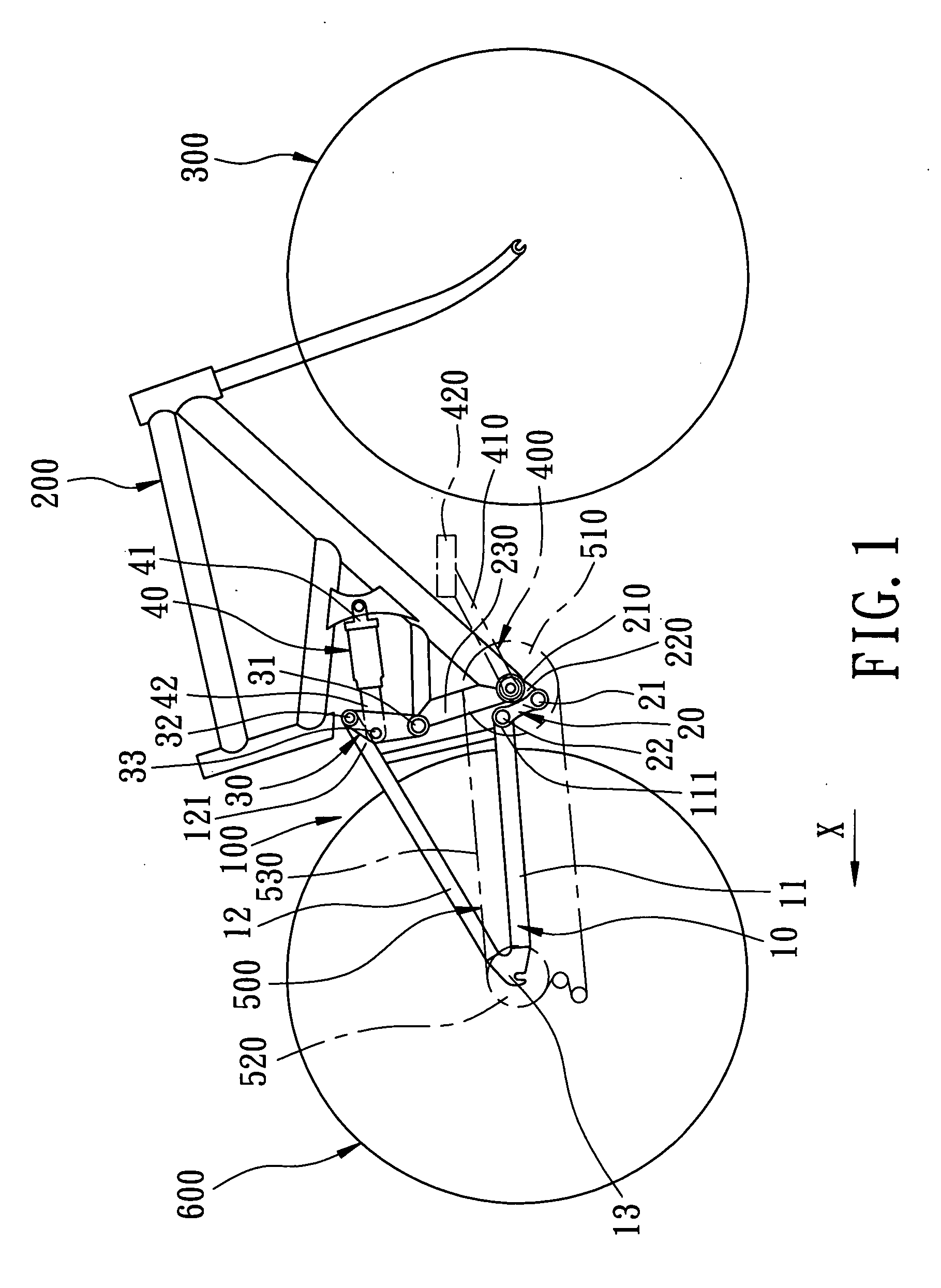
[0013] Referring to FIG. 1, the preferred embodiment of a bicycle rear suspension system 100 is disposed on a bicycle that includes a front triangular frame 200, a front wheel 300 disposed on a front end of the front triangular frame 200, a crank unit 400 disposed on a bottom portion of the front triangular frame 200, a drive unit 500 driven by the crank unit 400, and a rear wheel 600 disposed behind the front triangular frame 200 and supported by the suspension system 100. The suspension system 100 is used to absorb shock applied to the rear wheel 600. The front triangular frame 200 includes a crankshaft 210 disposed at a bottom portion thereof for connection with the crank unit 400, a rearwardly and downwardly inclined integral lower connecting rod 220 disposed below the crankshaft 210, and a rearwardly and upwardly inclined integral upper connecting rod 230 disposed above the crankshaft 210. The crank unit 400 includes a crank 410 and two pedals 420 connected respectively to two ...


PUM


Abstract

A bicycle rear suspension system has a virtual pivot point that is close to a junction between a chain and a front driving sprocket when a piston rod travels relative to a cylinder body by ¼ to ⅓ of a maximum displacement value, and that moves rearwardly when a rear wheel moves upwardly away from the ground. A line interconnecting an instant center of a rear triangular frame and a contacting point between a rear wheel and the ground forms an angle of about 45° with respect to a horizontal line.

Description

BACKGROUND OF THE INVENTION [0001] 1. Field of the Invention [0002] This invention relates to a bicycle, and more particularly to a bicycle rear suspension system. [0003] 2. Description of the Related Art [0004] U.S. Pat. No. 6,595,538 discloses a bicycle rear suspension system. Although the bicycle rear suspension system can effectively absorb shock applied to a rear wheel, it has a relatively complicated structure. SUMMARY OF THE INVENTION [0005] The object of this invention is to provide a bicycle rear suspension system that has a simple structure. [0006] According to this invention, a bicycle rear suspension system includes a rear triangular frame disposed behind a front triangular frame and supporting a rear wheel thereon, a pair of upper and lower links each interconnecting the front and rear triangular frames at two ends thereof, and a damping hydraulic cylinder having a front end connected pivotally to the front triangular frame, and a rear end connected pivotally to an inte...

Claims


Application Information

Patent Timeline
IPC IPC(8): B62K1/00B62K25/28
CPCB62K25/286
Inventor CHANG, OWENWU, LEO
Owner GIANT MFG
Why Eureka
Try Eureka