Remote sensing electric field exploration system

a remote sensing and electric field technology, applied in the direction of electric/magnetic detection for transportation, using reradiation, instruments, etc., can solve the problems of not achieving sufficient commercial acceptance to survive for more than a short period, lack of sophisticated instruments and digital data acquisition and processing systems that were not available, and achieve low cost. , the effect of minimal maintenance requirements

Inactive Publication Date: 2005-12-29
TELLURIC EXPLORATION
View PDF15 Cites 27 Cited by
  • Summary
  • Abstract
  • Description
  • Claims
  • Application Information

AI Technical Summary

Benefits of technology

[0018] Another object of the invention is it can be employed with a fixed network of electric field sensor stations on the ground in areas of earthquake hazards and volcanic eruptions for monitoring subsurface movements of fluids that may be prec

Problems solved by technology

However, airborne conductivity measurements of the underlying terrain made with airborne electromagnetic systems that currently exist, leave a great deal of room for improvement.
Although the AFMAG system showed some promise, it did not achieve sufficient commercial acceptance to survive for more than a short period.
Amongst the various problems of the system was the absence of the sophisticated instrumentation and digital data acquisition and processing systems that were not available at that time.
Also and very importantly, there was a lack of adequate technology for suppressing the prime sources of noise,

Method used


Image

  • Remote sensing electric field exploration system
  • Remote sensing electric field exploration system
  • Remote sensing electric field exploration system

Examples


Embodiment Construction

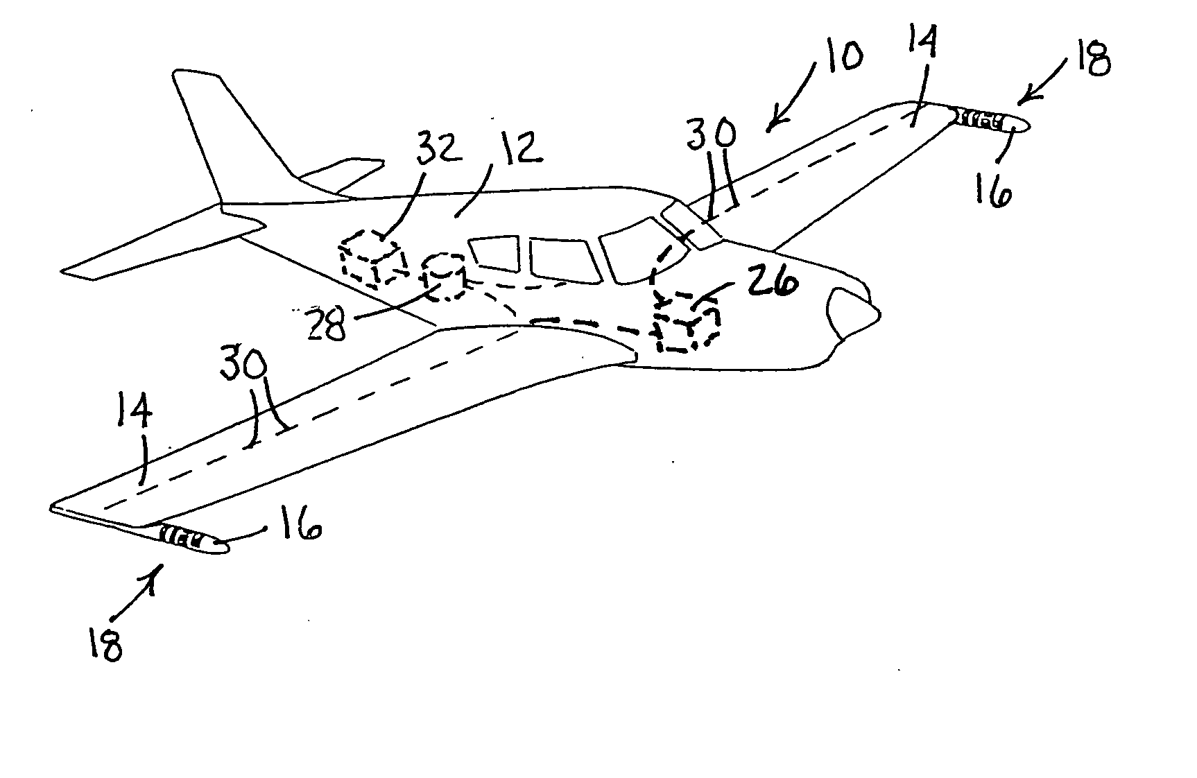
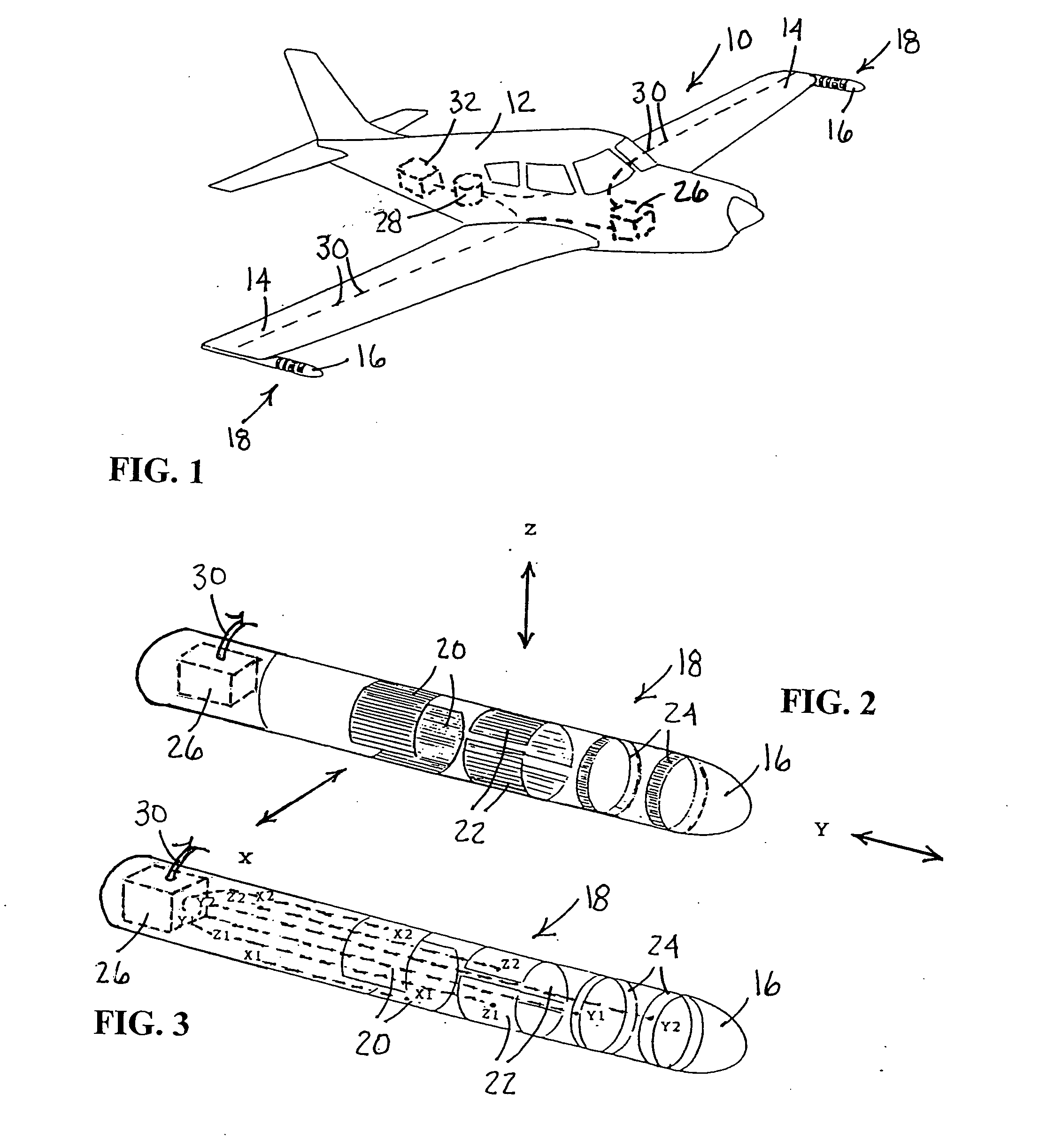
[0035] In FIG. 1, a perspective view of the subject airborne exploration system is shown having a general reference numeral 10. In this example, the exploration system 10 is mounted on a fixed wing aircraft 12. The aircraft 12 carries on each wing tip 14 an aerodynamic housing pod 16. Mounted on each of the pods 16 are electric field sensors, having general reference numeral 18. The electric field sensors 18 include three orthogonal dipoles 20, 22 and 24. The field sensor and dipoles are shown more clearly in FIGS. 2 and 3. The housing pod 16 is made to minimize drag and the impact of charged dust particles on the surfaces of the dipoles 20, 22 and 24. The sensors 18 are used in association with a triple set of 3-axis angular motion detectors 26 installed at the rear of each pod 16. The commercial angular motion detectors 26 are based on the use of vibrating quartz tuning forks and have an angular sensitivity of 0.003 degrees. The angular motion detectors are filly adequate for use ...


PUM


Abstract

An airborne exploration system used with an aircraft for shallow and deep exploration for oil and gas, mineral deposits and aquifers. The survey system uses natural electromagnetic EM fields as an energy source. The exploration system includes a pair of aerodynamic housing pods adapted for mounting on wing tips of the aircraft. The housing pods include electric field sensors with three orthogonal electric dipoles oriented along an X, Y and Z axis. An optional third set of orthogonal electric dipoles can be mounted in the tail of the aircraft. The field sensors are electrically attached to angular motion detectors mounted inside housing pods. The motion detectors are used for compensating for errors caused by angular motion of the aircraft when in the presence of strong electric field gradients. The system also includes a total field magnetometer mounted in the aircraft. The various filtered outputs of the magnetometer are used to provide phase and amplitude references for the similarly filtered and angular motion corrected outputs of the electric field sensors. The electric field data when normalized and phase referenced against the magnetic field data provides valuable geological and geophysical information related to the subsurface flow of telluric currents.

Description

[0001] This application is based on a provisional patent application filed in the U.S. Patent and Trademark Office on Jun. 24, 2004 having Ser. No. 60 / 582,185 by the subject inventor.BACKGROUND OF THE INVENTION [0002] (a) Field of the Invention [0003] The subject invention relates to an airborne survey aircraft or towed geophysical survey bird exploration system and more particularly, but not by way of limitation, to a remote sensing electric field exploration system for exploration of oil and gas, mineral deposits and aquifers and using natural electromagnetic fields as an energy source. This invention is also applicable to offshore exploration using a towed geophysical “fish” system. It is further applicable to the detection of per-curser events ahead of earthquakes and volcanic eruptions. [0004] (b) Discussion of the Prior Art [0005] Heretofore, airborne electromagnetic systems have been in use for natural resource exploration from about 1950 onwards. These systems depend mainly ...

Claims


Application Information

Patent Timeline
IPC IPC(8): G01V3/16G01V3/17
CPCG01V3/17G01V3/165
Inventor BARRINGER, ANTHONY R.
Owner TELLURIC EXPLORATION
Why Eureka
Try Eureka