Electric power monitoring and response system

a technology of electric power monitoring and response system, applied in the direction of instruments, electric devices, measurement using digital techniques, etc., can solve the problems of insufficient accuracy of measurement, inability to accurately and accurately measure the current of the high-voltage sensor, and high-voltage devices are quite expensive when applied at high-voltage. , to achieve the effect of improving the operation of response equipment, avoiding unnecessary and disruptive response actions, and more accurate and effective response actions

Inactive Publication Date: 2005-12-29
SOUTHERN STATES
View PDF7 Cites 46 Cited by
  • Summary
  • Abstract
  • Description
  • Claims
  • Application Information

AI Technical Summary

Benefits of technology

[0008] In other words, the invention solves the problem of inter-phase interference from multiple phase conductors by effectively solving the simultaneous equations necessary to determine the unknown system variables based on the measurements obtained from the field sensors. In some cases, the solution may use other known system values, such as distance values defining the distance from each field sensor to each phase conductor. One or more simplifying assumptions, such as balanced phase currents and equal physical sag, may also be used to reduce the number of field sensors. In addition, when the configuration of the power lines and the electromagnetic field sensors are known, the unknown system variables can be determined with a simple scaling and summing devices connected directly to the outputs of the sensors.
[0009] The resulting electric power monitoring and response system exhibits a number of important advantages over conventional systems. In particular, the field sensors are located “remotely beside” the phase conductors. In this description, the term “beside” means that each field sensor is located to one side, and thus does not surround, a phase conductor. It should be understood, however, that all of the field sensor need not be located to the same side of the phase conductors, but may be located anywhere in the electromagnetic field of the power line. The term “remotely” means that the sensors are located a significant distance from the phase conductors, preferably near the ground below the phase conductors. In practice, this allows inexpensive field sensors, such as Hall Effect magnetic field sensors, to be located sufficiently far away from the phase conductors to allow the ambient air to insulate the field sensors from the high-voltage power line. Unlike prior electric power monitoring techniques, this configuration is sufficient inexpensive to make the system economically feasible for wider range of power line voltages.
[0010] It should be appreciated that this type of electric power monitoring and response system using magnetic field sensors is not adversely affected by physical impediments such as weather, building, bridges, power line towers, substation equipment or other objects located in the magnetic fields because the magnetic field strength is not affected by these factors. This is a significant advantage, for example, when determining the values of the phase current in a power line located in a substation or in a multiple-line transmission line corridor where support structures, such as towers and substation equipment, are typically located within the magnetic field of the monitored power line.
[0011] It is often advantageous to locate the field sensors in positions where the distances from the sensors to the power lines does not change with system conditions. For example, the sensors can be located under the power line towers or in substations where the power lines are physically supported by overhead insulators. This allows the distances from the sensors to the power lines to be known values, which minimizes the number of sensors required to monitor the phase currents. Nevertheless, the system may also be employed to determine the physical sag experienced by a power line in a critical location by determining the distance of the phase conductors from the sensors measurements. This allows the power line physical sag to be monitored directly without relying on expensive optical equipment that can be adversely affected by weather and fouling by grime, bird droppings and the like.
[0013] This type of direct power system monitoring in critical locations improves the operation of the response equipment, avoids unnecessary and disruptive response actions in favor of more accurate and effective response actions, and generally results in the delivery of more reliable and higher quality power service. This type of system will also help to identify critical locations in which voltage support equipment is needed, as well as providing an very effective means for early detection and avoidance of cascading power outages, such at those affecting the Western, Midwestern and Northeastern United States in recent years. The system will also be an effective mechanism for identifying other types of potentially damaging power system disturbances, such as dynamic generation station oscillation, reactive power circulation, intermittent abnormal load behavior, lightening strikes, and so forth.
[0014] Generally described, the invention may be implemented as an electric power monitoring and response system for determining system variables associated with phase conductors of one or more multi-phase electric power line. The system includes a set of field sensors located remotely beside the phase conductors and positioned to simultaneously measure the combined electromagnetic fields generated by the phase conductors. In particular, the field sensors can be high-voltage insulated by ambient air by locating the sensors a sufficient distance away from the phase conductors to avoid a voltage breakdown between the phase conductors and the field sensors. The system also includes a controller configured to determine the system variables based on measurements received from the field sensors, and to produce output signals based on the system variables. The output signals are configured to cause response equipment to implement one or more response actions based on the output signals.

Problems solved by technology

While very accurate, these devices are quite expensive when applied at high voltages.
This results, in large part, from the need to insulate the current sensors for high-voltage, which is quite expensive for voltages above 1,000 volts.
In multiphase applications, this technique is complicated by magnetic field interference from the adjacent phases, which results in inaccurate measurements.
This approach also requires expensive high-voltage insulation for the magnetic field sensors, which makes the system economically feasible only at the highest transmission line voltages.
While this technique reduces the difficulty of insulating the current sensor at high voltages, the sophisticated decoding technology required to turn the polarization measurement into a current measurement is quite expensive.
Another type of power system unknown occurs because high currents and ambient air heat the electric conductors, which causes them to stretch and sag from their overhead supports.
If this sag becomes too large, a voltage breakdown and resulting flash over can occur between the power line and another object, such as a tree or hill.
But these algorithms only produce estimates of the physical sag at critical locations that can vary significantly from the actual conditions due to voltage drop and reactive power loading on the lined during high load conditions.
But these optical systems are very expensive, do not work well in the dark, can be adversely affected by bad weather and fouling by grime, bird droppings and the like.

Method used


Image

  • Electric power monitoring and response system
  • Electric power monitoring and response system
  • Electric power monitoring and response system

Examples


Embodiment Construction

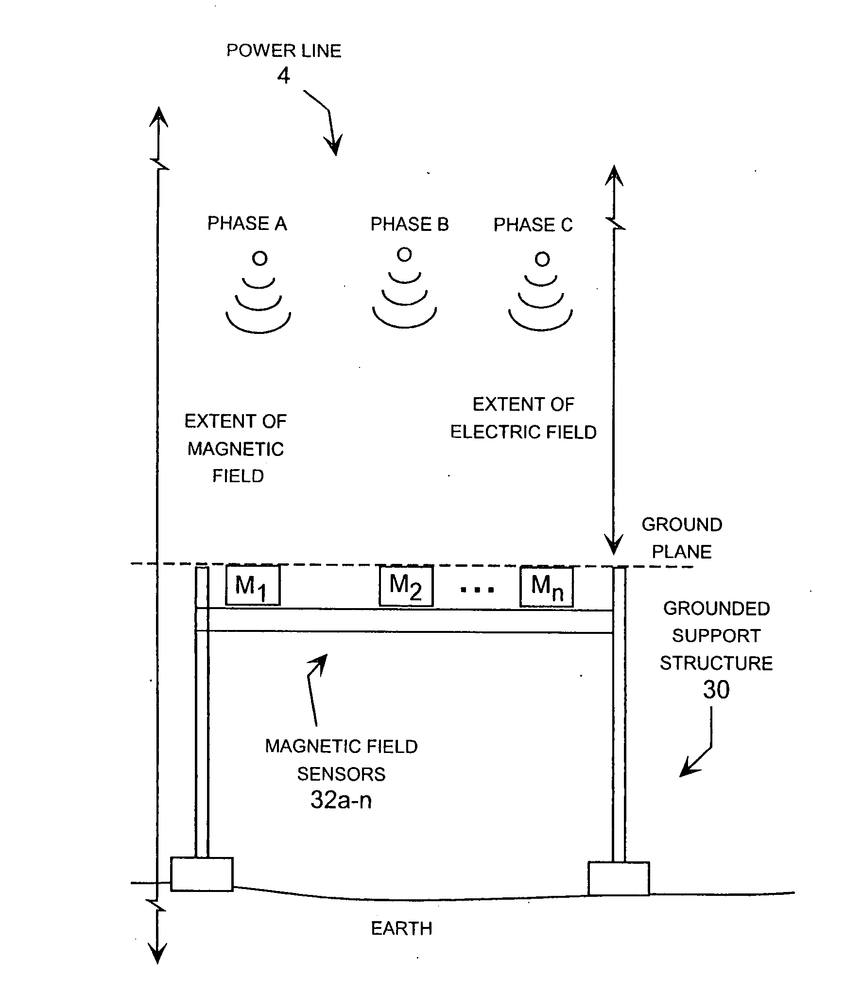
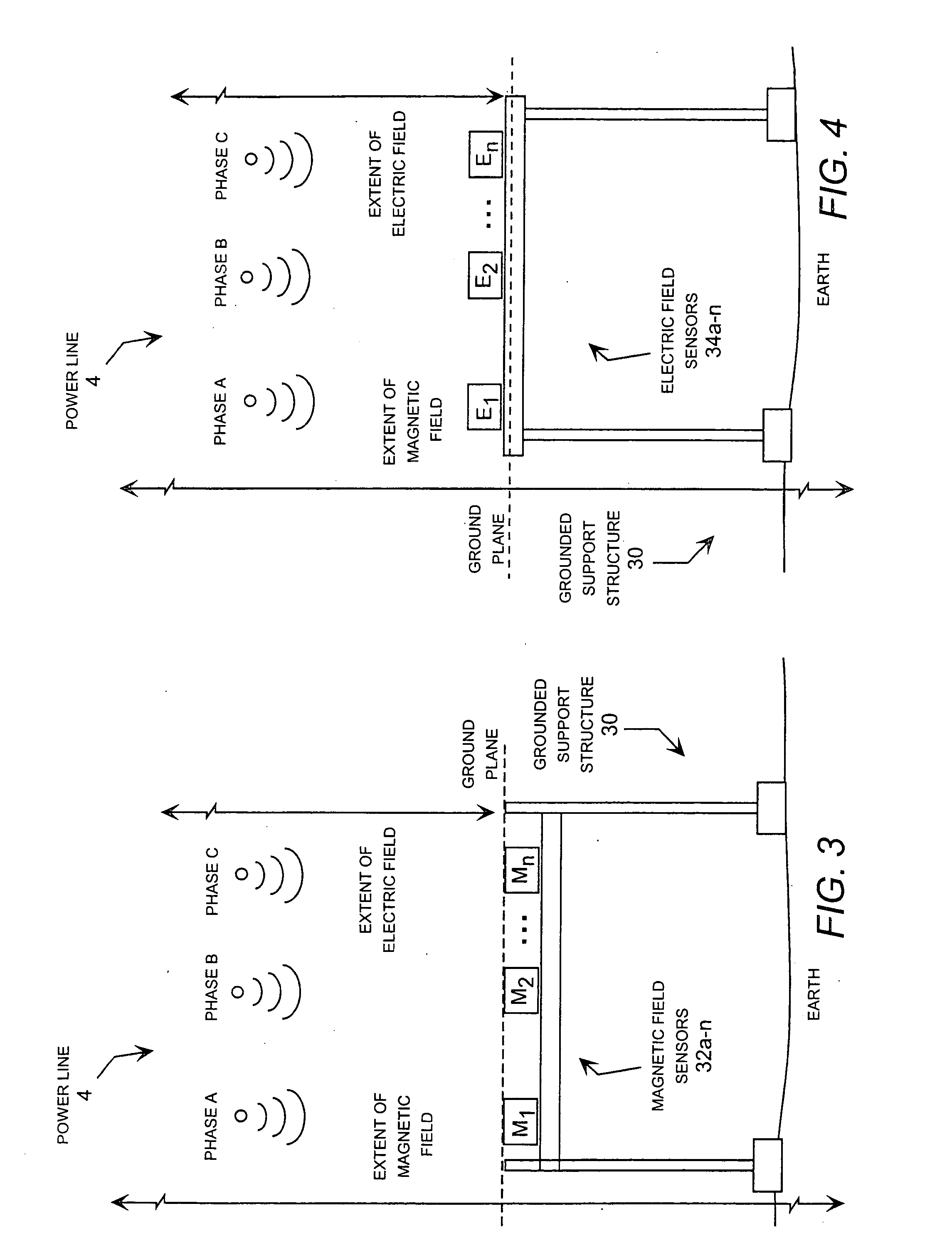
[0029] The present invention provides significant improvements in monitoring and fault protection equipment for multi-phase electric power lines. The specific embodiments use inexpensive magnetic field sensors, such as Hall Effect sensors, that are physically located beside (i.e., not surrounding) and removed from the phase conductors by a considerable distance. Preferably, the field sensors are located at or near the ground itself and at ground potential. This solves the high-voltage electrical insulation problem by using atmospheric air the insulating medium, which avoids special expensive insulation for the sensors. The measured magnetic field values received from the magnetic field sensors are combined with mathematical relationships and, in some cases.

[0030] To implement the system, a set of equations is derived for computing the values of a number of unknown system variables from an equal or greater number of measured sensor values. In general, the system variables may includ...


PUM


Abstract

An electric power monitoring and response system using electromagnetic field sensors located remotely beside the phase conductors. The system determines unknown system variables for one or more three-phase power lines based on measured values obtained form the field sensors and, in some cases, known power system values. For a given physical configuration, the field sensors may include a magnetic or electric field sensors, and the known system values as well as the unknown system variables may include phase currents, phase voltages and distances defining the physical configuration of the system. The response equipment may be a display, a circuit interrupting device, a voltage regulator, a voltage sag supporter, a capacitor bank, communication equipment, and reporting system.

Description

PRIORITY CLAIM TO RELATED APPLICATION [0001] This application claims priority to commonly-owned United States Provisional Patent Application Ser. No. 60 / 583,907 entitled “Multiple Phase Current Sensor With Remote Multiple Sensors,” filed on Jun. 29, 2004, which is incorporated herein by reference.TECHNICAL FIELD [0002] The present invention relates to the field of high voltage electric power transmission and distribution systems, and more particularly to an electric power monitoring and response system that uses remotely located electromagnetic field sensors to determine unknown power system variables, such as the phase currents, phase voltages and / or the distances from the field sensors to the phase conductors. BACKGROUND OF THE INVENTION [0003] At present, ring-type current transformers (“CTs”) are the most prevalent technology for measuring phase currents in three-phase electric power transmission and distribution lines. While very accurate, these devices are quite expensive when...

Claims


Application Information

Patent Timeline
Patent Type & Authority Applications(United States)
IPC IPC(8): G01R15/14G01R15/20G01R19/25G06F19/00H02G1/02
CPCG01R15/142G01R19/2513G01R15/20
Inventor ROSTRON, JOSEPH R.ANAND, RAJKEISTER, LYLE THOMAS
Owner SOUTHERN STATES
Why Eureka
Try Eureka