QKD system network

a technology of system network and key distribution, applied in the field of quantum cryptography, can solve the problems of relays that must be trusted, qkd networks have their own drawbacks, and the configuration is relatively complicated and expensiv

Inactive Publication Date: 2005-12-29
MAGIQ TECH INC
View PDF2 Cites 93 Cited by
  • Summary
  • Abstract
  • Description
  • Claims
  • Application Information

AI Technical Summary

Problems solved by technology

As a consequence, an eavesdropper (“Eve”) that attempts to intercept or otherwise measure the quantum signal will introduce errors into the transmitted signals, thereby revealing her presence.
Such QKD networks do have their own drawbacks, however.
For example, their prime weakness is that the relays must be trusted.
However, this configuration is relatively complicated and expensive because it requires two QKD stations for the relay station 30.
Replicating this configuration for an even larger commercially viable QKD network very quickly becomes an expensive and unwieldy proposition.

Method used


Image

  • QKD system network
  • QKD system network
  • QKD system network

Examples


Embodiment Construction

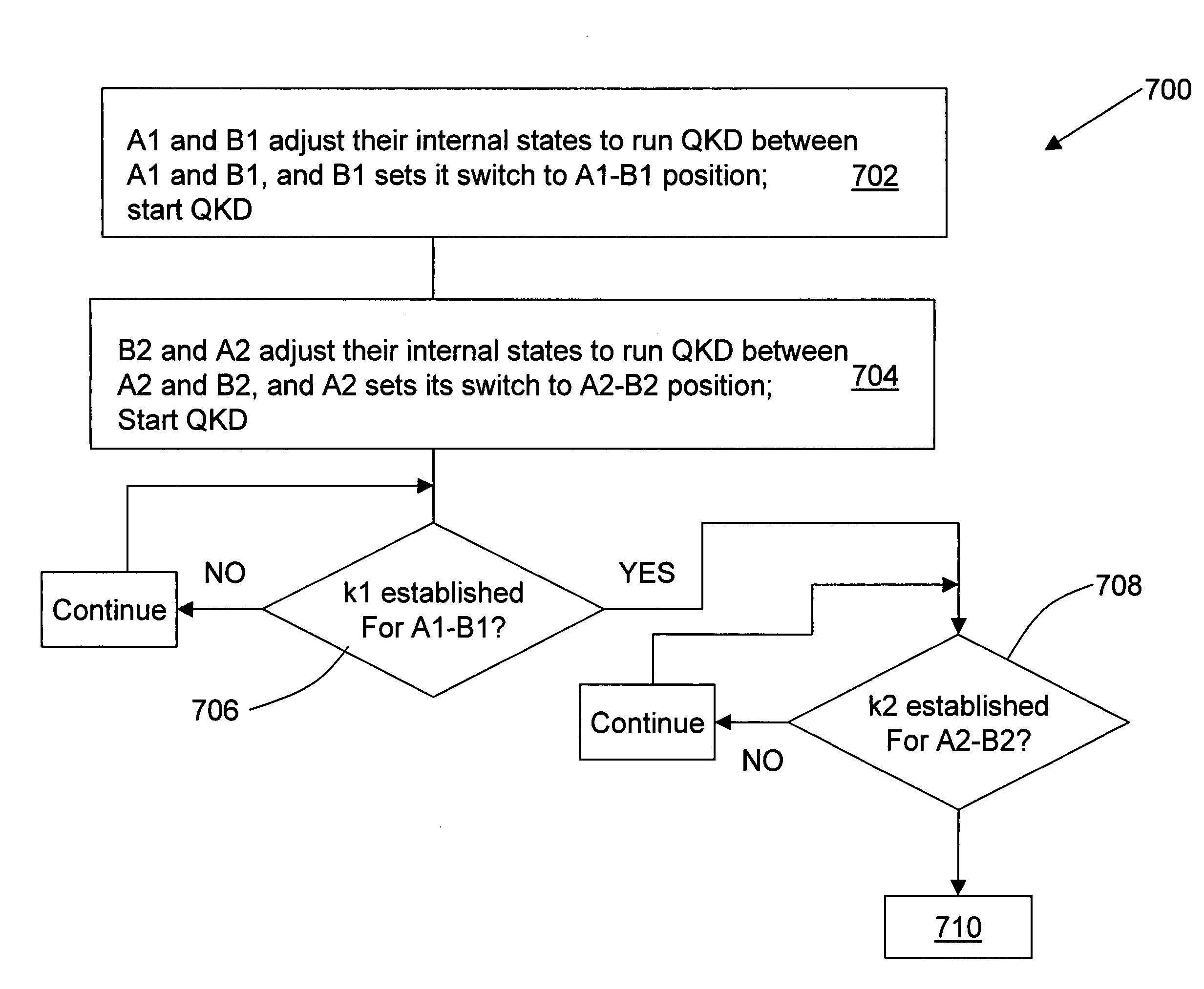
[0028] The present invention allows for a chain of intermediate (“relay”) stations to be organized in a less expensive manner than prior art QKD system networks by adding optical path switches to the Alice and / or Bob QKD stations (“boxes”) between the two end-users. The switches allow for the relay stations to have a single QKD station that interacts with adjacent QKD stations depending on the state of the optical switch.

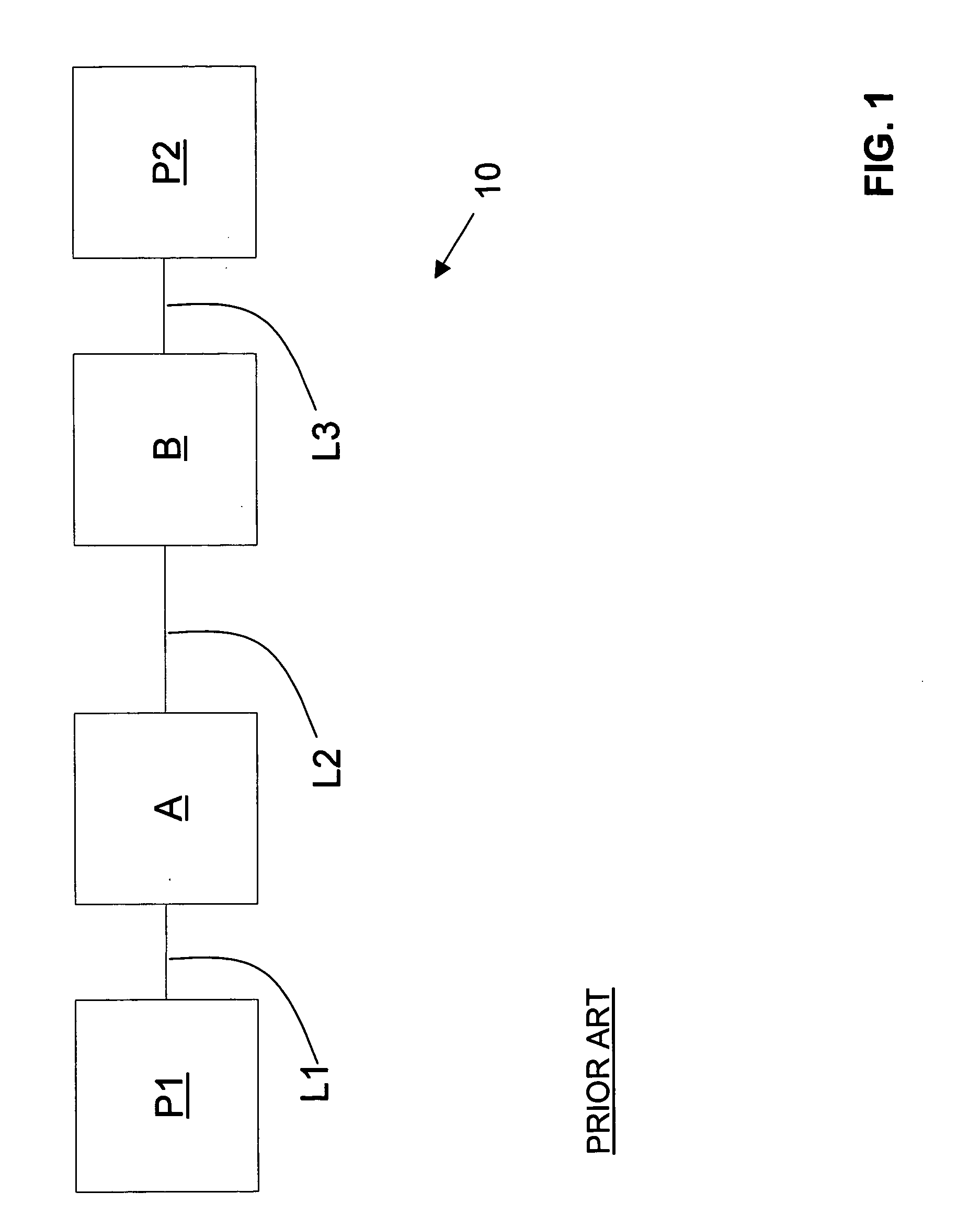
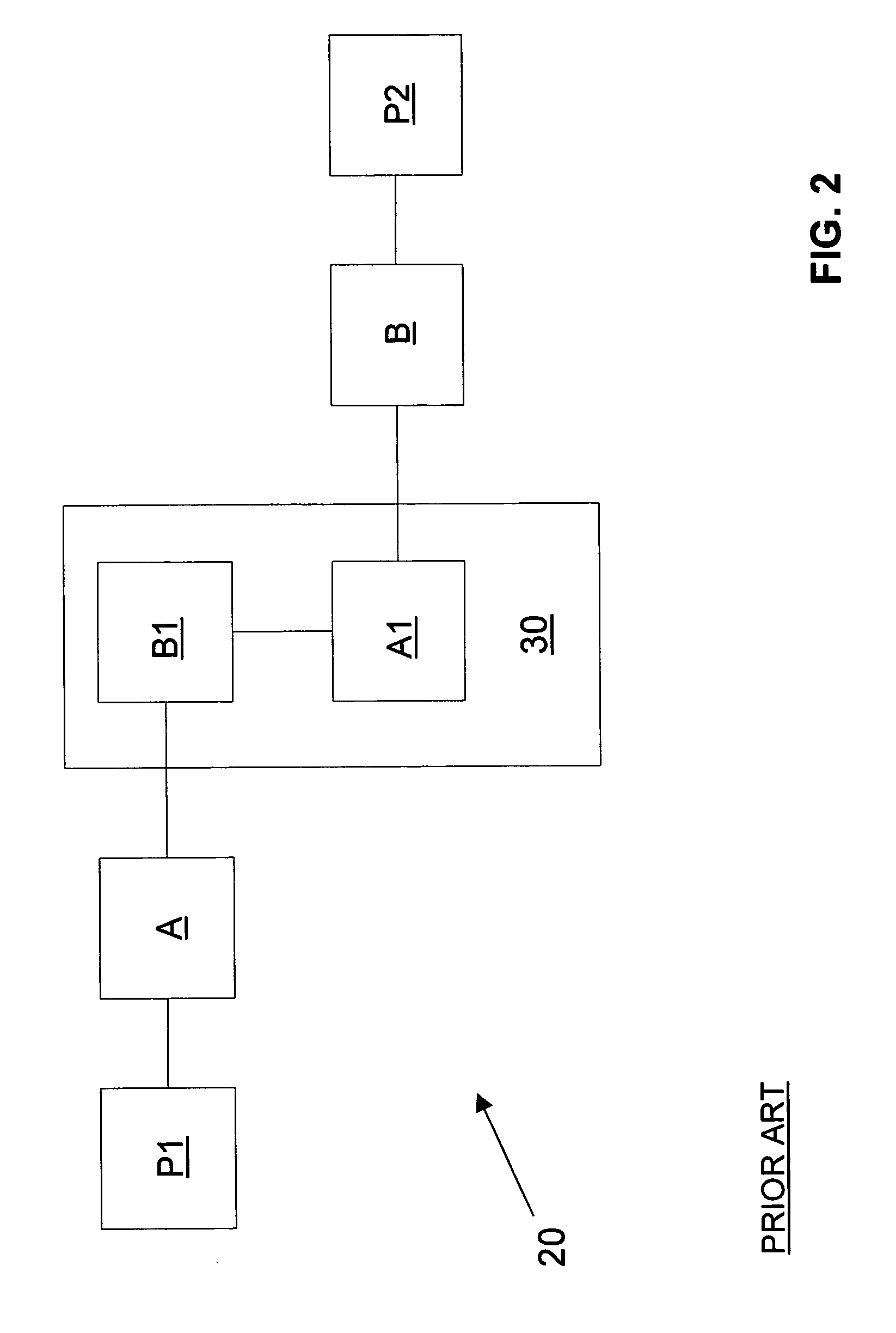
[0029]FIG. 3 is a schematic diagram of a QKD system 50 according to the present invention. QKD system includes an optically-lined cascaded chain of boxes A1, B and A2. The configuration of QKD system 50 can be represented in shorthand as P1-A1-B-A2-P2, wherein P1 and P2 are the end-users operably coupled to respective QKD stations A1 and A2 via links LA1 and LA1. In the QKD system 50, only Bob (B) is connected to or includes an optical switch 55 that allows B to establish a connection with either A1 or A2, e.g., via optical fiber links F1, F2 and F3. This arrangeme...


PUM


Abstract

QKD system networks (50, 200, 300) and methods of communicating between end-users (P1, P2) over same are disclosed. An example QKD system network (50) includes a first QKD station (A1) and a second QKD station (A2) with a relay station (58) in between. The relay station includes a single third QKD station (B) and an optical switch (55). The optical switch allows the third QKD station to alternately communicate with the first and second QKD stations so as to establish a common key between the first and second QKD stations. The end-users are coupled to respective QKD stations A1 and A2. A secret key (S) is shared between P1 and P2 by QKD station B being able to independently form keys with A1 and A2. This basic system, represented as P1-A1-B-A2-P2, can be expanded into more complex linear networks, such as P1-A1-B1-A2-B2-P2 with B1 and A2 making up the relays. The basic QKD system network can also be expanded into multi-dimensions.

Description

CLAIM OF PRIORITY [0001] This application claims priority from U.S. Provisional Patent Application No. 60 / 583,515, filed on Jun. 28, 2004.FIELD OF THE INVENTION [0002] The present invention relates to quantum cryptography, and in particular relates to a quantum key distribution (QKD) system network. BACKGROUND OF THE INVENTION [0003] Quantum key distribution involves establishing a key between a sender (“Alice”) and a receiver (“Bob”) by using weak (e.g., 0.1 photon on average) optical signals transmitted over a “quantum channel.” The security of the key distribution is based on the quantum mechanical principle that any measurement of a quantum system in unknown state will modify its state. As a consequence, an eavesdropper (“Eve”) that attempts to intercept or otherwise measure the quantum signal will introduce errors into the transmitted signals, thereby revealing her presence. [0004] The general principles of quantum cryptography were first set forth by Bennett and Brassard in th...

Claims


Application Information

Patent Timeline
Patent Type & Authority Applications(United States)
IPC IPC(8): H04B10/516H04B10/61H04B10/70H04L9/00H04L9/08
CPCH04L9/0855
Inventor VIG, HARRYBERZANSKIS, ANDRIUS
Owner MAGIQ TECH INC
Why Eureka
Try Eureka