Printing unit

a printing unit and printing technology, applied in the field of printing units, can solve the problems of large space occupation, large maintenance work, and large size of printing units incorporated in such information terminals, and achieve the effect of simple in itself, complicated maintenance work, and simple replacement of rolled sheets

Inactive Publication Date: 2005-12-29
SEIKO EPSON CORP
View PDF10 Cites 15 Cited by
  • Summary
  • Abstract
  • Description
  • Claims
  • Application Information

AI Technical Summary

Benefits of technology

[0007] It is therefore an object of the invention to provide a printing unit in which a simple structure allows a front portion of the apparatus to be freed for the pur

Problems solved by technology

As a result, printing units that are incorporated in such information terminals are also required to be small and occupy a small installation space.
The back side and the right and left sides of the kiosk terminal are also parts of the important floor space, and it is not appropriate to keep these spaces unoccupied as dead spaces for maintenance.
As a result, even such maintenance work as rolled sheet replacement, which is simple in itself, beco

Method used


Image

  • Printing unit
  • Printing unit
  • Printing unit

Examples


first embodiment

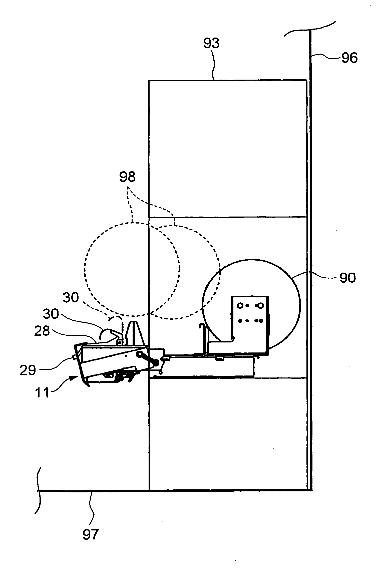
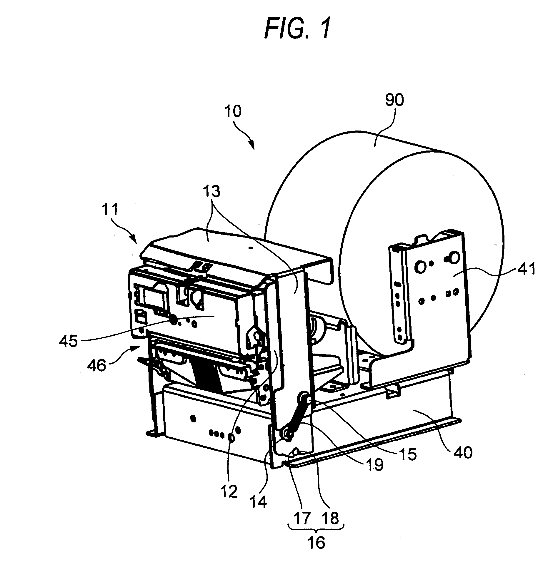
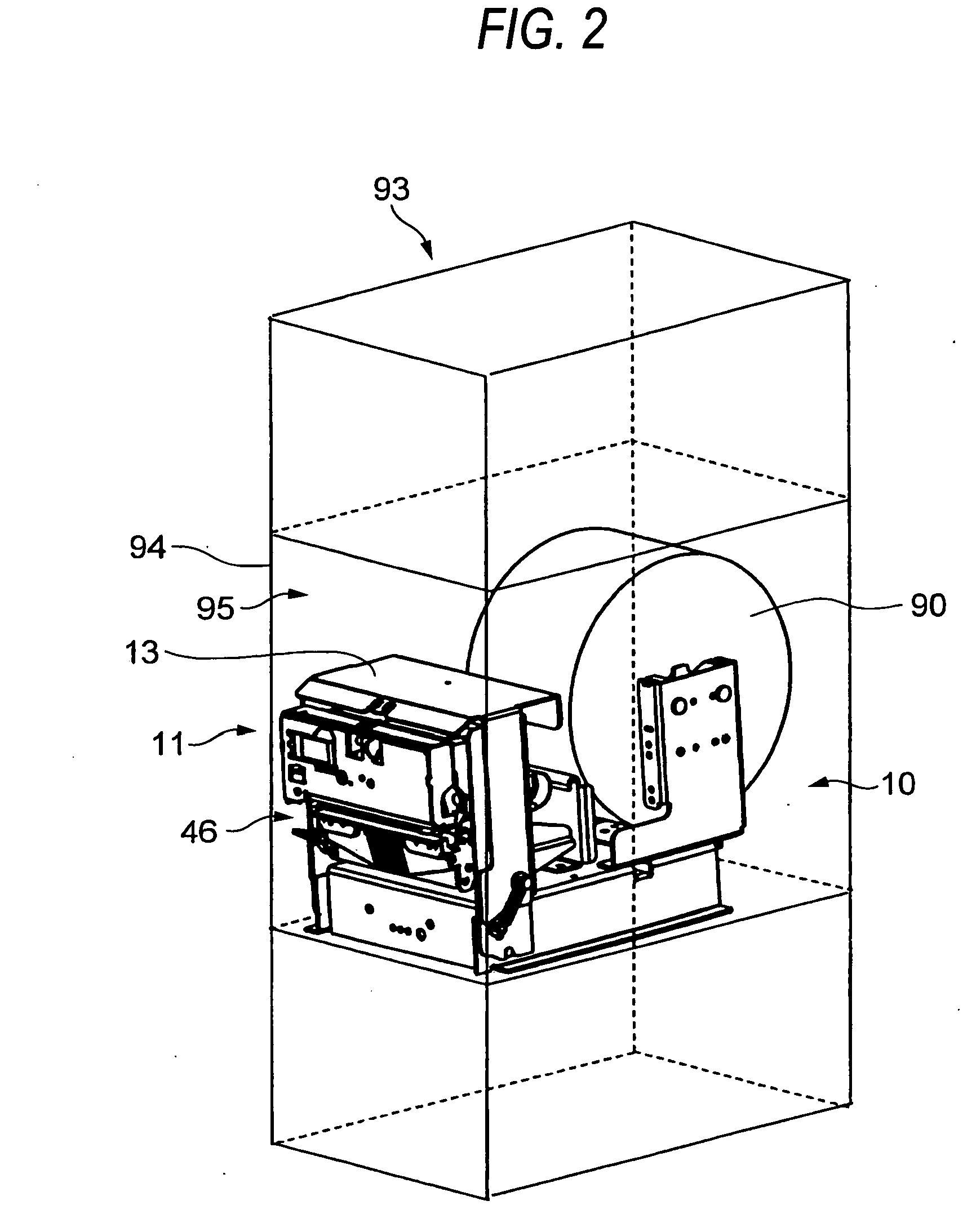
[0076]FIG. 1 shows a printing unit 10 according to the invention. In this embodiment, the printing unit 10 is equipped with a front section 11 that is pivotable outward, a base frame 40, and a rolled sheet holder 41 for holding a rolled sheet 90 inside the printing unit 10. The front section 11 includes a release lever 13 and a movable frame 12 and is lifted up by pulling, to the front side, the release lever 13 that is provided on the front side of the apparatus. As a result, the movable frame 12 is unlocked and can be pivoted forward. Therefore, by pulling the release lever 13 to the front side together with the movable frame 12, the entire front section 11 is tilted forward. Since the movable frame 12 can be unlocked and the front section 11 can be tilted forward merely by such a simple manipulation (pulling the release lever 13 to the front side), the front portion can be easily freed with one hand. Although the front portion can be freed by pulling the release lever 13 to the f...

second embodiment

[0108]FIGS. 15 and 16 show a printing unit according to the invention. This printing unit is different from the printing unit 10 of FIGS. 1 to 14 in the release lever 32 and the buffer plate 30 escape mechanism. In this embodiment, the release lever 32 is provided with projections 35, and an actuator shaft 36 extending parallel with the buffer plate 30 is attached to the tip portions of the projections 35. The buffer plate 30 is provided with, on both sides, a link portion 37 having a hole. The actuator shaft 36 is attached to the release lever 32 in a state that it penetrates through the holes of the link portions 37. Therefore, the release lever 32 is connected to the buffer plate 30 via the link portion 37, and the projections 35, the actuator shaft 36, and the link portions 37 constitute a link mechanism. When the release lever 32 is pivoted counterclockwise, the actuator shaft 36 rotates counterclockwise about the second shafts 15 which are the pivot centers of the release leve...

third embodiment

[0110] FIGS. 17 to 19 show a printing unit according to the invention. This printing unit is different from the printing units of FIGS. 1 to 16 in the buffer plate 30 escape mechanism.

[0111] In this embodiment, the release lever 80 is inclined inward by a prescribed angle in the locked state. The release lever 80 is provided with an actuator plate 81 that is bent at a prescribed angle and serves to actuate the buffer plate 30. The buffer plate 30 is pivotally supported by the movable frame 12 via the pivot shaft 31, and is provided with, in its rear, an engagement portion 38 that is bent upward and engages with the actuator plate 81.

[0112] With the above structure, when the release lever 80 is pivoted, the actuator plate 81 pushes the engagement portion 38 counterclockwise and thereby causes the buffer plate 30 to escape to the position shown in FIG. 19. In this embodiment, it is possible to cause the buffer plate 30 to escape without using a wire by a simpler mechanism than in the...


PUM


Abstract

A first frame member has an accommodating section adapted to accommodate a rolled sheet at a rear side of the first frame member. A print head is operable to perform printing with respect to a part drawn out from the rolled sheet. A second frame member is provided with the print head and supported on a front side of the first frame member so as to be movable between a first position and a second position. A locking mechanism locks the second frame member at the first position. A release lever releases the locked state of the second frame member when the release lever is pulled toward the second frame member. User access with respect to at least the accommodating section is allowed when the second frame member is placed in the second position.

Description

BACKGROUND OF THE INVENTION [0001] The present invention relates to a printing unit that is incorporated in an installation type information terminal such as a kiosk terminal or an automatic teller machine (ATM). [0002] There are various kinds of installation type information terminals, such as a kiosk terminal that is installed in a railroad station, airport, a convenience store, or the like, an ATM, a counting and recording terminal that is installed in a parking lot, a gas station, or the like, that print prescribed information on recording paper and issue a resulting sheet, or a ticket reservation and issuance machine for a theater ticket or the like. To print prescribed information such as details of a deal or purchase or ticket reservation information on prescribed paper and issue a resulting sheet, such installation type information terminals incorporate a printing unit that accommodates a roll of recording paper (rolled sheet). [0003] In many cases, such installation type in...

Claims


Application Information

Patent Timeline
IPC IPC(8): B41J15/04B41J29/02B41J29/13G07F19/00G07G5/00
CPCB41J15/042B41J29/02G07G5/00G07F19/20G07F19/201B41J29/13G06F3/12
Inventor SUZUKI, KUNIYUKIMOMOSE, JIRO
Owner SEIKO EPSON CORP
Why Eureka
Try Eureka