
System and method for storing and discharging hydrogen

a hydrogen storage and hydrogen technology, applied in the direction of electrochemical generators, transportation and packaging, packaging goods types, etc., can solve the problems of not being able to fill the storage vessel with usable hydrogen in a reasonably short time period, and affecting the efficiency of hydrogen storage and discharging

Inactive Publication Date: 2005-12-29
GENERAL ELECTRIC CO
View PDF9 Cites 44 Cited by
  • Summary
  • Abstract
  • Description
  • Claims
  • Application Information

AI Technical Summary

Problems solved by technology

One of the challenges in utilizing hydrogen has been the need for simple, efficient, reliable and cost-effective techniques for compressing, storing and releasing hydrogen.
Ineffective heat removal can cause the hydrogenation process to slow down or terminate.
Unless heat is effectively removed from the metal hydride powder when hydrogen is added to the storage vessel, it may not be practical to fill the storage vessel with usable hydrogen in a reasonably short time period.
Consumers will not be motivated to use hydrogen as a fuel if it takes an unreasonably long time to refuel the on-board hydrogen storage vessel of the vehicle.
A related issue is that heat also needs to be generated to release stored hydrogen when the hydrogen fuel stored in a storage vessel is used.
The process of heat removal from a bulk of the storage bed is slow because it relies on the heat conduction through metal hydride powder, which is a poor heat conductor.
Heat conduction is usually highly restricted through a powdery storage bed typical for metal hydrides and therefore results in slow charging of hydrogen in the metal hydride.
In addition, the complex distribution lines for the cooling medium such as water or the like results in excess increase in the overall weight of the storage system.
This additional weight reduces the effectiveness of hydrogen systems for use in vehicles.

Method used


Image

  • System and method for storing and discharging hydrogen
  • System and method for storing and discharging hydrogen
  • System and method for storing and discharging hydrogen

Examples


Embodiment Construction

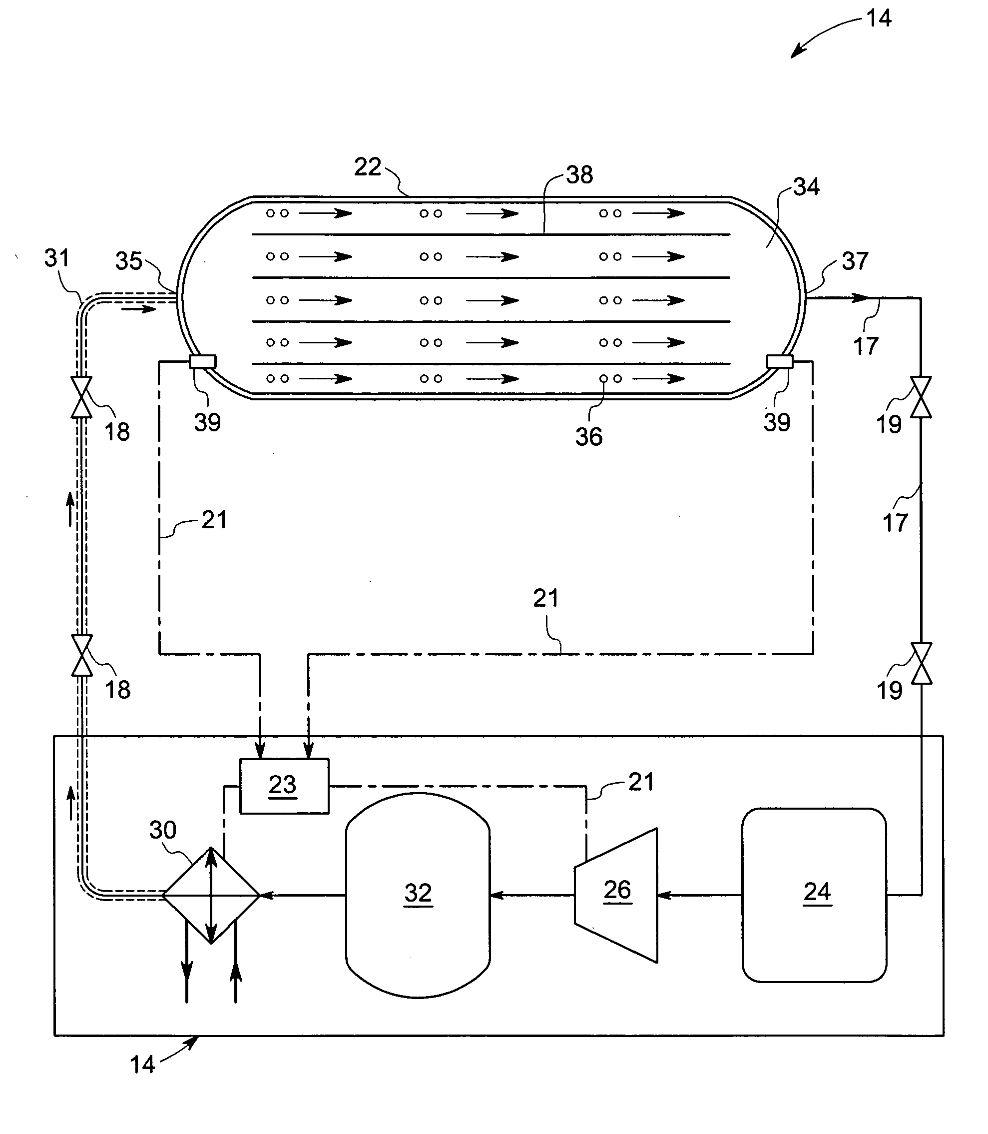
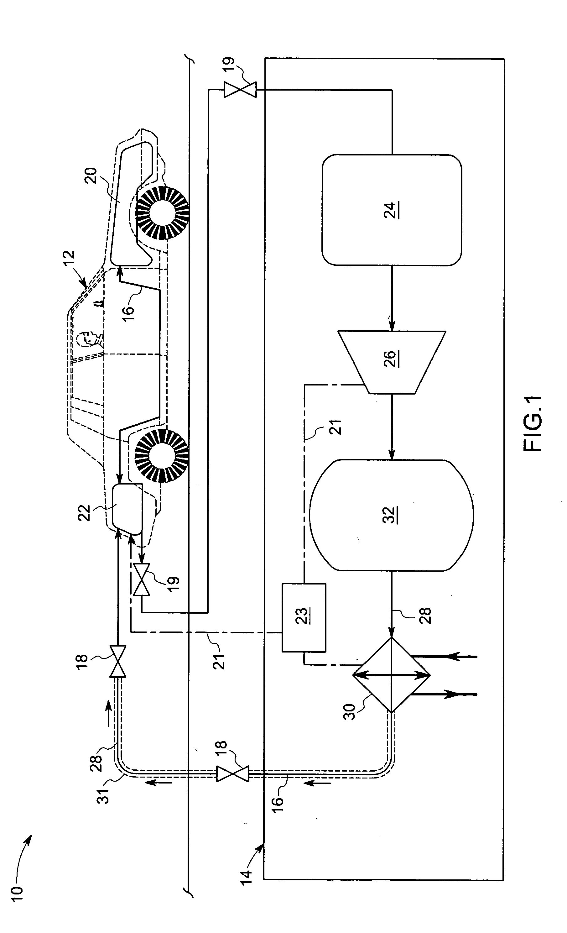
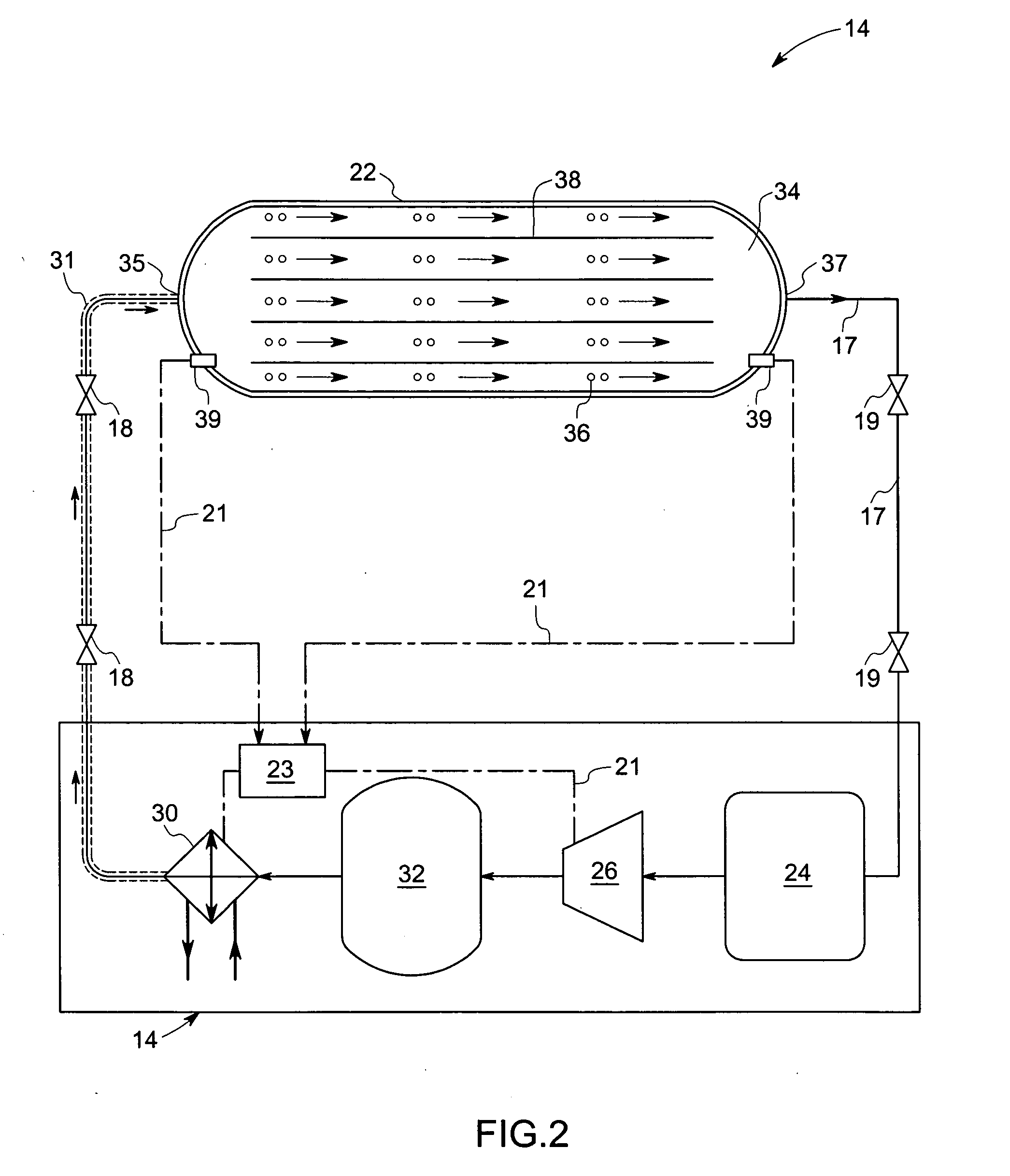
[0016] The present technique discloses a system and method for charging and discharging hydrogen from a hydrogen storage vessel with a heat transfer system. In one embodiment, the hydrogen storage vessel is disposed on a vehicle for use in providing fuel to the power conversion unit of the vehicle. In the description of the figures below, like features are designated with like reference numerals in each figure where possible.

[0017] Turning now to the drawings, FIG. 1, illustrates a hydrogen fuel system 10. The hydrogen fuel system 10 comprises a vehicle 12 and a hydrogen filling system 14 connected by a plurality of interconnecting pipelines 16 and 17 for transfer of hydrogen between the hydrogen fuel system 10 and the vehicle 12. A plurality of valves 18 and 19 is provided for flow control of hydrogen. Those of ordinary skill in the art will appreciate that the positions shown for the valves 18 and 19 are a matter of design choice and not an essential aspect of the present techniq...


PUM

PropertyMeasurementUnit
Pressureaaaaaaaaaa
Flow rateaaaaaaaaaa
Flexibilityaaaaaaaaaa

Abstract

A hydrogen fuel system comprises an open gas circuit that includes a source of hydrogen. The hydrogen fuel system also includes a compressor that forces a flow of hydrogen from the source of hydrogen through the open gas circuit, and a hydrogen storage vessel comprising an inlet and an outlet. The hydrogen fuel system may also include a hydrogen storage bed being disposed within the hydrogen storage vessel between the inlet and the outlet, the hydrogen storage vessel being adapted to form a portion of the open gas circuit so that the hydrogen storage bed is cooled by convection while hydrogen flows through the open gas circuit.

Description

BACKGROUND [0001] The invention relates generally to a system and method for the efficient storing and discharging of hydrogen in a hydrogen storage system. [0002] Hydrogen is currently considered as a potentially useful energy source. One of the challenges in utilizing hydrogen has been the need for simple, efficient, reliable and cost-effective techniques for compressing, storing and releasing hydrogen. [0003] It is generally known that hydrogen may be stored in compressed gaseous form in pressure vessels or at low temperature as liquid hydrogen. It is also known that hydrogen may be stored in storage vessels that contain powdered metal hydrides. The collection of metal hydrides in a storage vessel is referred to as a bed. Metal hydrides comprise metal atoms that constitute a host lattice. The host lattice traps hydrogen atoms in interstitial sites, such as lattice defects. Storage of hydrogen as a solid hydride provides greater volumetric storage density compared to that of compr...

Claims


Application Information

Patent Timeline
IPC IPC(8): H01M8/04H01M8/06
CPCH01M8/04089H01M8/04208Y02E60/50H01M8/065H01M8/04216F17C11/005Y02P90/45Y02E60/32
Inventor BUSHKO, WIT CEZARY
Owner GENERAL ELECTRIC CO
Learn More