Cyclic transmission of notification coordinates in a communication system

Inactive Publication Date: 2005-12-29
PANASONIC CORP
1 Cites 58 Cited by

AI-Extracted Technical Summary

Problems solved by technology

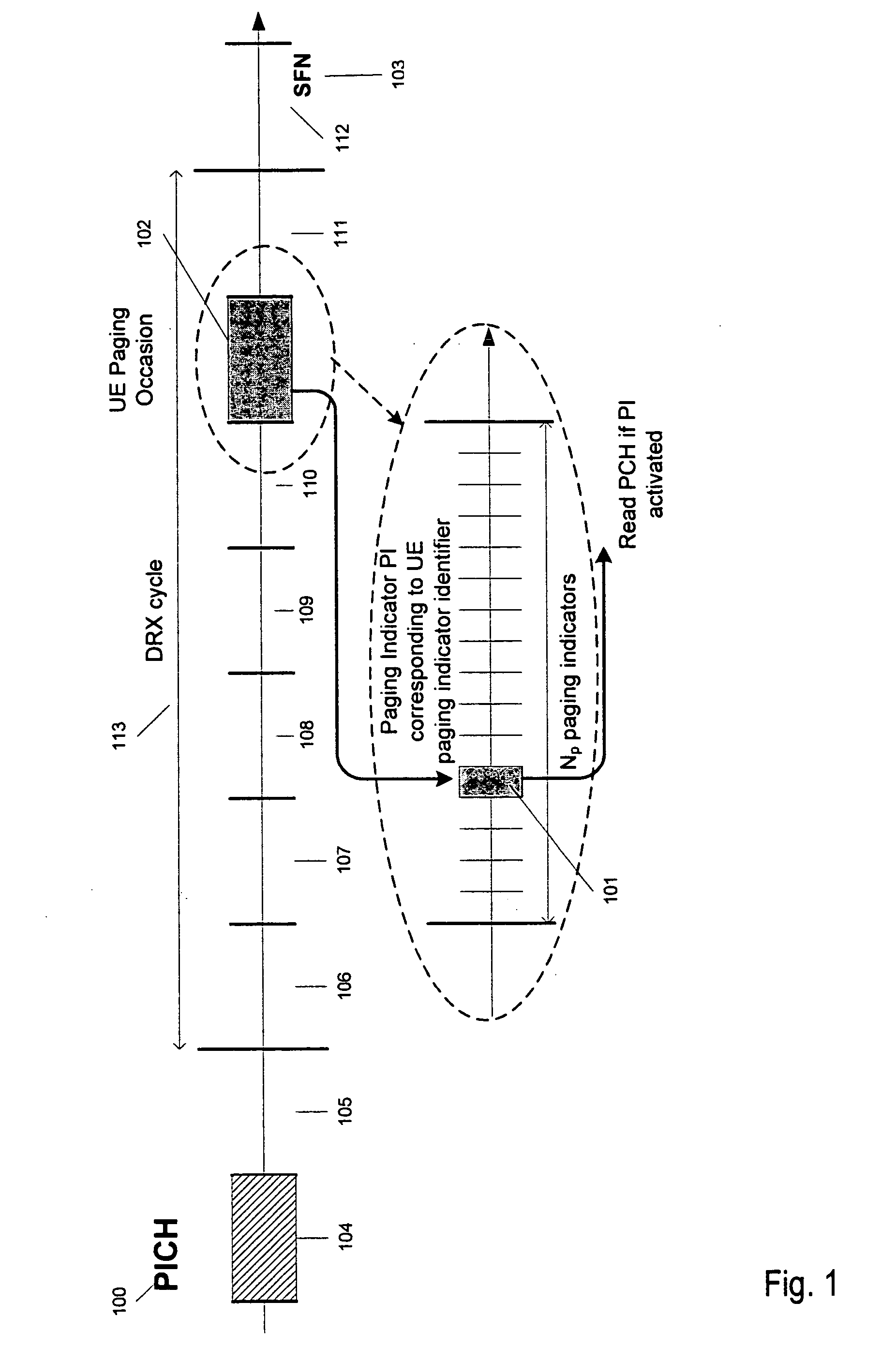
A missed event occurs when the UE fails to detect a paging message because of decoding errors due to an unreliable interface between the transmitter and the receiver.
A false alarm can be caused by an unreliable interface.
Unfortunately, this parameter has an opposite effect on the probability of false alarm, and a trade-off is necessary between Pf and Pm.
Unfortunately, these design targets might contradict each other, and typically a trade-off is needed between UE battery consumption and the probability of false alarm.
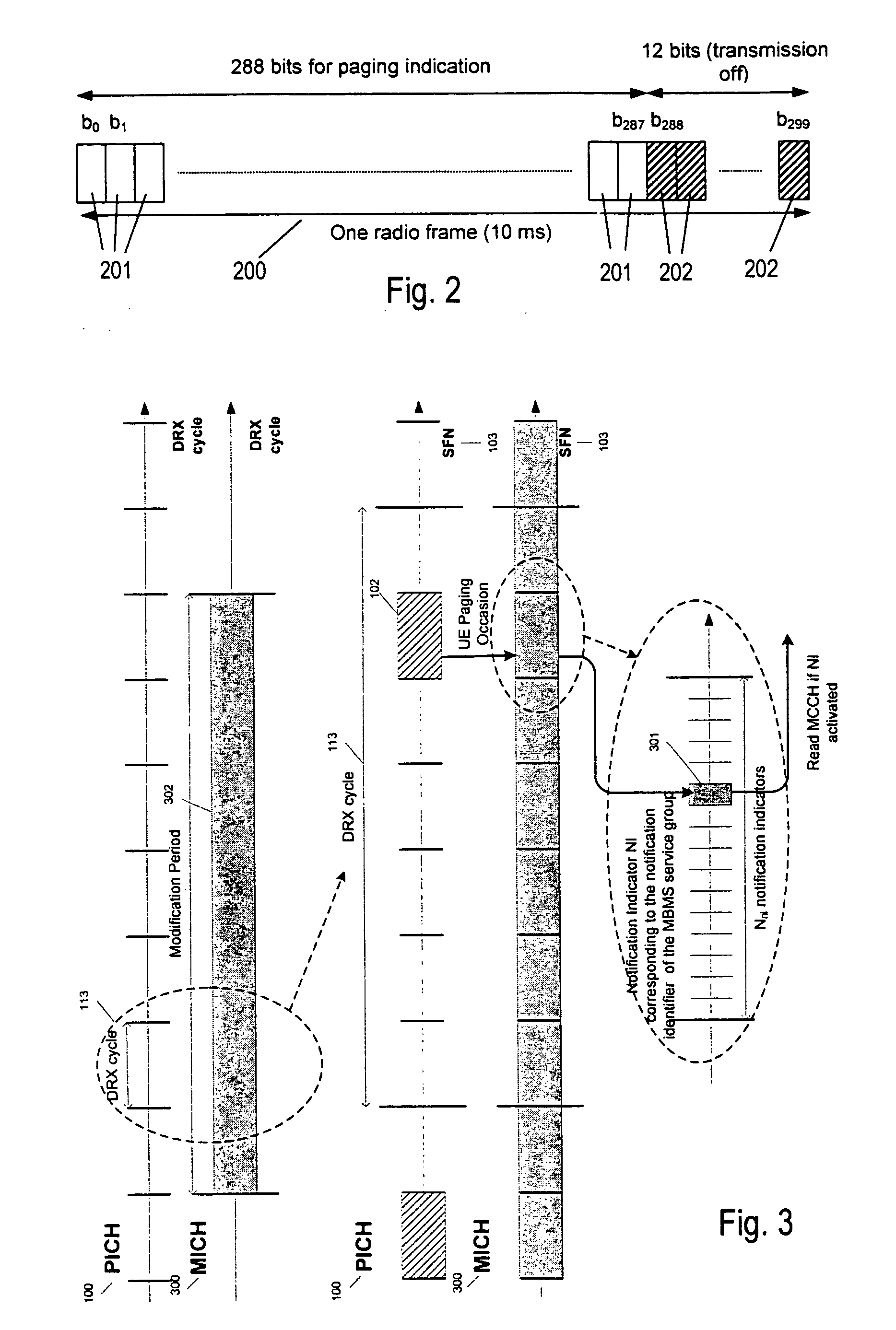
Frequent MICH readings might decrease the probability of false alarm, improve the signalling robustness and decrease the notification delay time, but would severely impact the UE power consumption.
This would however hav...

Benefits of technology

[0040] It is the object of the present invention to provide a notification mechanism based on a MICH structure that guaran...

Abstract

A method for notification in communication systems is disclosed, in which a sequence of K notification indicators is assigned to a notification identifier like for example a MBMS service identifier or service group identifier of UMTS. The K notification indicators are transmitted one per frame in a cyclic manner. To obtain the notification indicator identifiers indexing the notification indicators in each frame, the plurality of notification identifiers is arranged in a K-dimensional space. Each of the K coordinates of this space can assume Nni values, where Nni is the number of notification indicators signalled per frame. The ith coordinate Xi,n of the point to where the nth notification sequence is mapped in the K-dimensional space, forms the identifier for the notification indicator belonging to the nth notification sequence in the frame with the frame number satisfying the equation i=M mod K.

Application Domain

Technology Topic

Real-time computingGroup identifier +2

Image

  • Cyclic transmission of notification coordinates in a communication system
  • Cyclic transmission of notification coordinates in a communication system
  • Cyclic transmission of notification coordinates in a communication system

Examples

  • Experimental program(1)

Example

[0054] The illustrative embodiments of the present invention will be described with reference to the figure drawings, wherein like elements and structures are indicated by like reference numbers.
[0055] The present invention presents a new method for a multi-frame notification messaging based on cyclic transmission of notification coordinates. This method will be called herein below the “cyclic notification sequence method”.
[0056] Although the method according to the present invention can be applied to various wired and wireless networks requiring notification and having a framed data structure, it will explained below without loss of generality for the example of MBMS notification in UMTS, like defined by the 3GPP. Other applications are conceivable with wired local area networks or wireless networks of other standards. For example, notifications could be used to wake up devices of a wired local area network.
[0057] Referring now to FIG. 6, a space 600 is considered containing notification sequences of finite length K. In the example shown in FIG. 6, K has a value of 3. The following equation gives the number of possible notification sequences:
Nbnotification — sequence=NniK,   (6)
[0058] Depending on the number of generated notification sequences, in 3GPP a notification sequence will be associated to a specific MBMS service group or may directly identify an MBMS service. This will depend on the sequence length and on the number of notification indicators per frame. For example, with Nni=18 and K=6, the number of notification sequences will be greater than the number of MBMS service identifiers currently foreseen in 3GPP TS 29.846v1.3.1, which would make the introduction of MBMS service group unnecessary.
[0059] As illustrated in FIG. 6, the space 600, which represents a plurality of notification identifiers (for example MBMS service group identifiers or MBMS service identifiers), can be seen as a K-dimensional space, and each notification identifier can be identified by a set of K coordinates as follows n = ∑ i = 0 K - 1 ⁢ X i , n ⁢ N ni i , ( 7 )
where Xi,n ε[0, Nni-1] and n is the notification identifier of the nth notification sequence.
[0060] It is proposed to transmit the ith notification indicator identifier of the nth notification sequence with a notification indicator identified by the coordinate Xi,n 601, 602, 603 within the frame identified by SFN based on the following rule If SFN mod K =i Then activate the Xi,nth notification indicator on MICH End
[0061] The coordinates Xi,n 601, 602, 603 can be easily computed by the network and the UE. One possibility for computing the Xi,n coordinates is given by the following set of iterative equations.
Xo,n=n mod Nni
∀i ε [1, K−1], Xi,n=[(n mod Nnii+1)−Xi-1,n]div Nni,   (8)
where mod and div are the modulo and the integer division operations.
[0062] Another possibility is given by the following equation.
∀i ε [0, K−1], Xi,n=(n mod Nnii+1)div Nnii.   (9)
[0063] It shall be noted that both solutions are equivalent.
[0064] The proposal presented above has the same probability of false alarm, assuming a perfect decoding of the indicators mapped on the MICH as the indicator sequence method proposal if the length of the notification sequence is the same as the number of indicators read by the UE (indicator sequence method). Analytical and simulation results are shown in table 2 and the simulation assumptions are presented in table 3. TABLE 2 Probability of false alarm Pfand mean time between 2 false alarms Indicator sequence & cyclic Mean time notification Mean time Indicator between 2 sequence between 2 combination false alarms methods false alarms K method in s. K = 2 in s. 1 25% 0.04 25% 0.04 2 19% 0.05 6.2% 0.16 3 20% 0.05 1.5% 0.65 4 24% 0.04 0.4% 2.50
[0065] TABLE 3 Simulation assumptions for the probability of false alarm simulations Parameter Name Value Number of tries 100000 Number of announced MBMS service 50 Distribution of MBMS service ID Uniform UE Receiver performance Error free Number of indicator within 1 MICH frame (Np) 36 Number of MBMS services notified per frame 5 Number of MBMS services monitored by the UE 1
[0066] As an example, a system is now regarded with Nni=18 notification indicators per frame. With a sequence length of K=3, 183=5832 notification identifiers can be distinguished. If a service has been assigned the notification identifier 3277, the Cartesian coordinates, and therefore the identifiers of the notification indicators, of which the sequence consists, are [0067] X0,3277=3277 mod 18=1 [0068] X1,3277=( (3277-1) div 18) mod 18=182 mod 18=2 [0069] X3,3277=( (182-2) div 18) mod 18=10 mod 18=10. [0070] In a frame with SFN 1713, [0071] i=1713 mod 3=0,
therefore in the case of a notification the notification indicator indexed with X0,3277=1 would be set to positive. In the next frame, the notification indicator indexed with X1,3277=2 would be set to positive and in the following frame the notification indicator indexed with X3,3277=10 would be set to positive. The same would be repeated in a cyclic manner ever frame until the end of the notification period.
[0072] Referring now to FIG. 7, an example with K=2 is shown. The space 700 can be seen as a square of side Nni and X0,n 701 and X1,n 702 are the well known (x,y) coordinates.
[0073] The nth notification sequence is identified by
n=yNp+x, (10)
and the coordinates are easily calculated as follows { ⁢ x = n ⁢ ⁢ mod ⁢ ⁢ N ni ⁢ y = n ⁢ ⁢ div ⁢ ⁢ N ni . ( 11 )
[0074] It should be highlighted that the presented way of calculating the K coordinates Xi,n is not unique and several other ways are possible (e.g. starting with the highest coordinates as proposed in Equation (9). The precise choice of particular equations to calculate the K coordinates has no significant impact on the overall complexity or on the UE power consumption. This calculation is only performed once when the UE is signalled the MBMS service identifier it should monitor.
[0075] Depending on the number of notification sequences, the notification identifier is associated to an MBMS service group identifier or directly to an MBMS service identifier.
[0076] In other applications of the invention, the notification identifier might also be an identifier of the device itself.
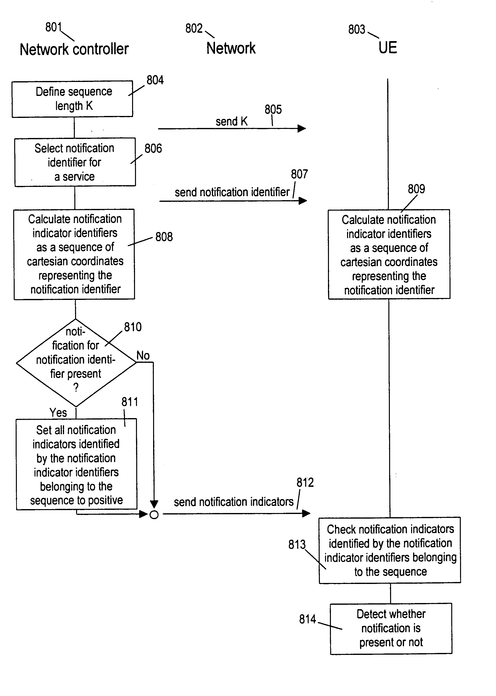
[0077] Referring now to FIG. 8, an exemplary flow chart is shown, employing the method according to the present invention. Three columns show the activities of a first network device 801 which might be a network controller, a second network device 803, which might be a UMTS UE and a network 802 connecting both. First, network controller 801 defines a sequence length K in step 804 and transmits it over network 802 to UE 803 in step 805. It is assumed that UE 803 has subscribed to a service which has been assigned a notification identifier, for example a service identifier or service group identifier in step 806. UE 803 is informed about this identifier in step 807. K can without problem be re-defined after the notification identifier has been assigned and transmitted. Therefore steps 804 and 805 can also be performed after steps 806 and 807. Now both devices can calculate the sequence of notification indicator identifiers like explained above in steps 808 and 809.
[0078] Note that only K and the notification identifier have to be informed to UE 803. If the UE is switched off and switched back on after a longer time, it usually only needs to receive information about K and can determine directly and without other synchronisation than a frame number the notification indicator identifier of the sequence belonging to the actual frame, using the frame number broadcast in the network and the equations above.
[0079] If a notification is present for the given notification identifier (“YES” in 810), for example because new data is available to be transmitted, the network controller subsequently sets the notification indicators, one of each frame, identified by the calculated notification indicator identifiers, to positive in step 811. For notification of other notification identifiers, other notification indicators or even the same may be set to positive within the same frame. As all notification indicators had been initialised to negative, this corresponds to a disjunction between all notifications. All notification indicators are broadcast over the network in step 812. They can be received by UE 803 within a suitable time interval. The notification indicators identified by the notification indicator identifier belonging to the sequence can then be checked for their contents and the presence of a respective notification can be detected. In this context, one frame is to be understood as the time unit within which one notification indicator of a sequence is transmitted. This could be a UMTS frame, but also any smaller or larger time unit like for instance a UMTS subframe.
[0080] In FIG. 9 an exemplary structure of a device 900 of a communication system is shown, which can send notifications according to the method described above. Among other elements, like processor 903 and interfaces 904, 905 to other networks, it may comprise a notification generator 901 to generate the notification indicators as described above and a network interface 902 to send them, among other data, via a communication network. The notification generator 901 may advantageously be implemented in software to be carried out in a general purpose processor.
[0081] A device 1000 of a communication system, adapted to receive and detect notifications sent by device 900, is shown in FIG. 10. It comprises a network interface 1001 to receive notification indicators and other information from the network, and a notification detector 1002 to detect notifications from the received notification indicators. It may further comprise components like processor 1003, display 1004 and keyboard 1005, which are not required to carry out the present invention. Notification detector 1002 may be implemented in software to be carried out in a general purpose processor.
[0082] Another embodiment of the present invention relates to the implementation of the above described various embodiments using hardware and software. It is recognized that the various above mentioned methods as well as the various logical blocks, modules, circuits described above may be implemented or performed using computing devices, as for example general purpose processors, digital signal processors (DSP), application specific integrated circuits (ASIC), field programmable gate arrays (FPGA) or other programmable logic devices, etc. The various embodiments of the present invention may also be performed or embodied by a combination of these devices.
[0083] Further, the various embodiments of the present invention may also be implemented by means of software modules which are executed by a processor or directly in hardware. Also a combination of software modules and a hardware implementation may be possible. The software modules may be stored on any kind of computer readable storage media, for example RAM, EPROM, EEPROM, flash memory, registers, hard disks, CD-ROM, DVD, etc.
[0084] Various embodiments as described above may advantageously reduce the probability of missed notification and false alarm in MBMS notification. Thus, battery consumption of mobile devices can be reduced.
[0085] While the invention has been described with respect to the embodiments constructed in accordance therewith, it will be apparent to those skilled in the art that various modifications, variations and improvements of the present invention may be made in the light of the above teachings and within the purview of the appended claims without departing from the spirit and intended scope of the invention. In addition, those areas in which it is believed that those of ordinary skill in the art are familiar, have not been described herein in order to not unnecessarily obscure the invention described herein. Accordingly, it is to be understood that the invention is not to be limited by the specific illustrative embodiments, but only by the scope of the appended claims.

PUM

no PUM

Description & Claims & Application Information

We can also present the details of the Description, Claims and Application information to help users get a comprehensive understanding of the technical details of the patent, such as background art, summary of invention, brief description of drawings, description of embodiments, and other original content. On the other hand, users can also determine the specific scope of protection of the technology through the list of claims; as well as understand the changes in the life cycle of the technology with the presentation of the patent timeline. Login to view more.

Similar technology patents

Tailgate with reversing camera

Owner:GM GLOBAL TECH OPERATIONS LLC

Methods for diagnosing zika virus

InactiveUS10210955B1Low probabilityImage enhancementImage analysisHigh probabilityLow correlation
Owner:ARSH BANERJEE

Light-receiving element and display device

ActiveUS20090159893A1Enlarge regionLow probabilitySolid-state devicesOpticsDisplay deviceSemiconductor
Owner:JAPAN DISPLAY WEST

Method for generating identification numbers

InactiveUS6991176B1Low probabilityUser identity/authority verificationCoding/ciphering apparatusPersonal identification numberComputer hardware
Owner:DEUTSCHE TELEKOM AG

Classification and recommendation of technical efficacy words

Why Eureka
Try Eureka