
Dealer identification system

a dealer identification and dealer technology, applied in the field of dealer identification systems, can solve the problems of sporadic introduction of technology, inconsistent design, and often ill-designed, and achieve the effects of simple casino table gaming devices and systems, limited scope, and inconsistent design

Inactive Publication Date: 2005-12-29
SHUFFLE MASTER
View PDF58 Cites 76 Cited by
  • Summary
  • Abstract
  • Description
  • Claims
  • Application Information

AI Technical Summary

Benefits of technology

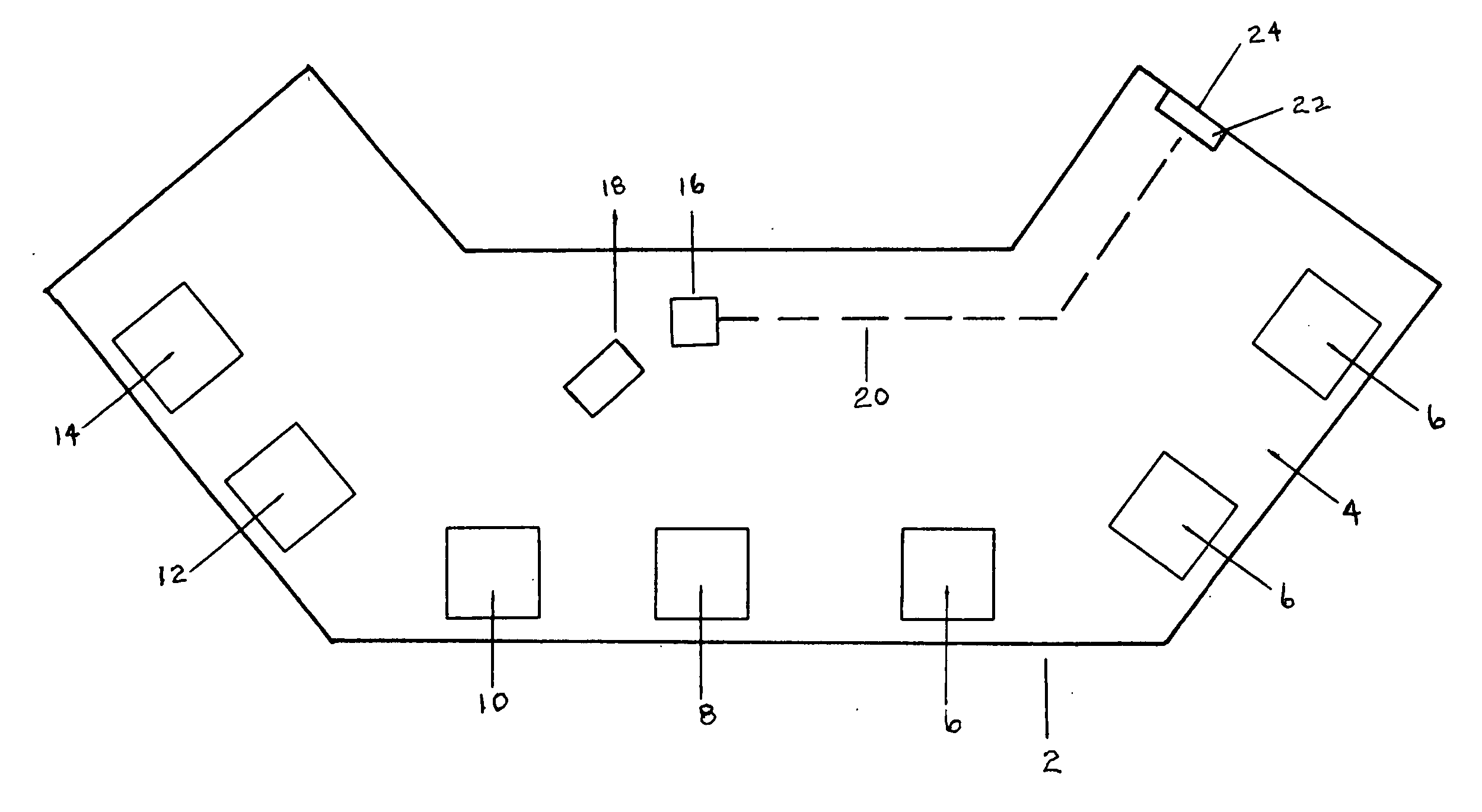
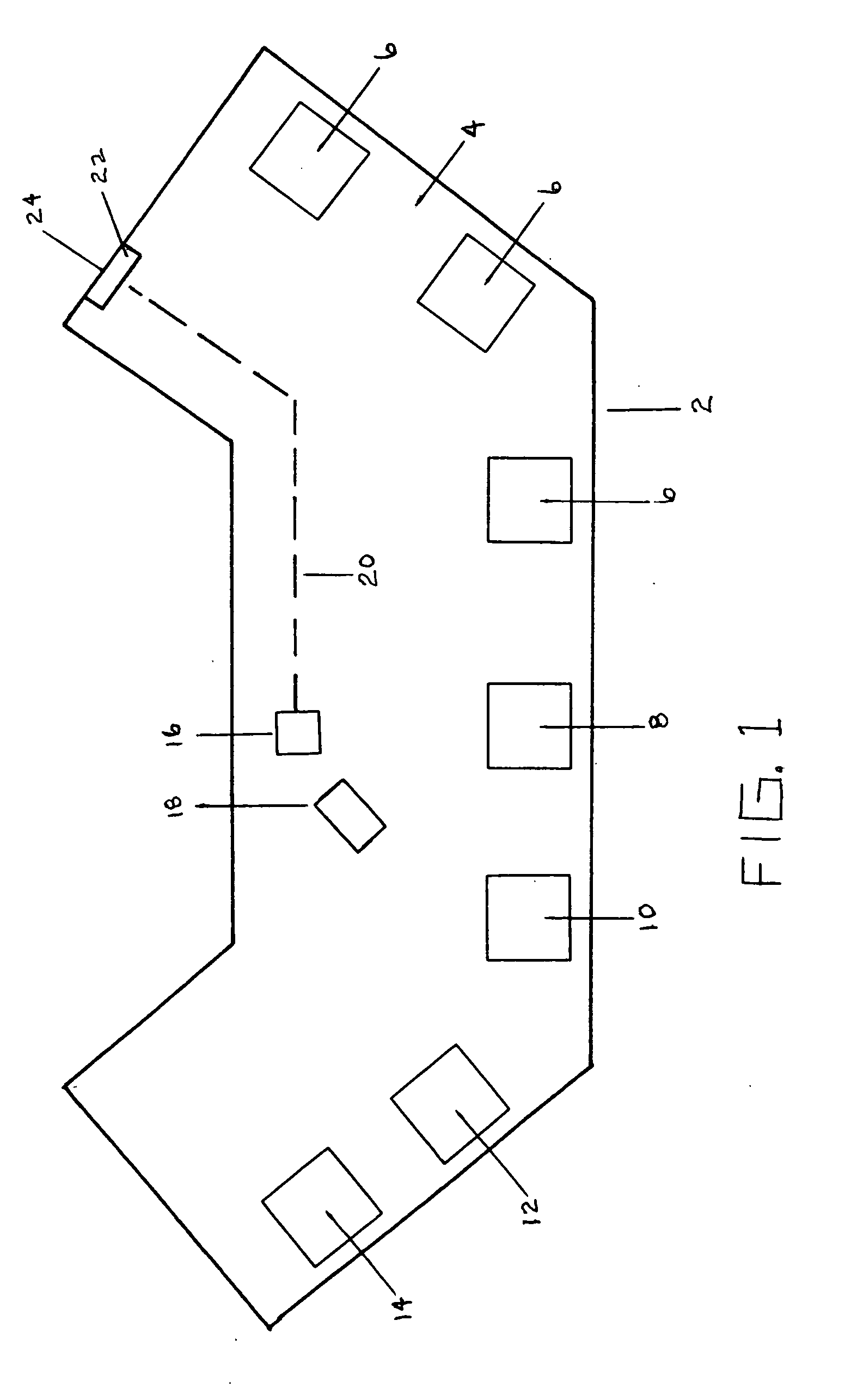
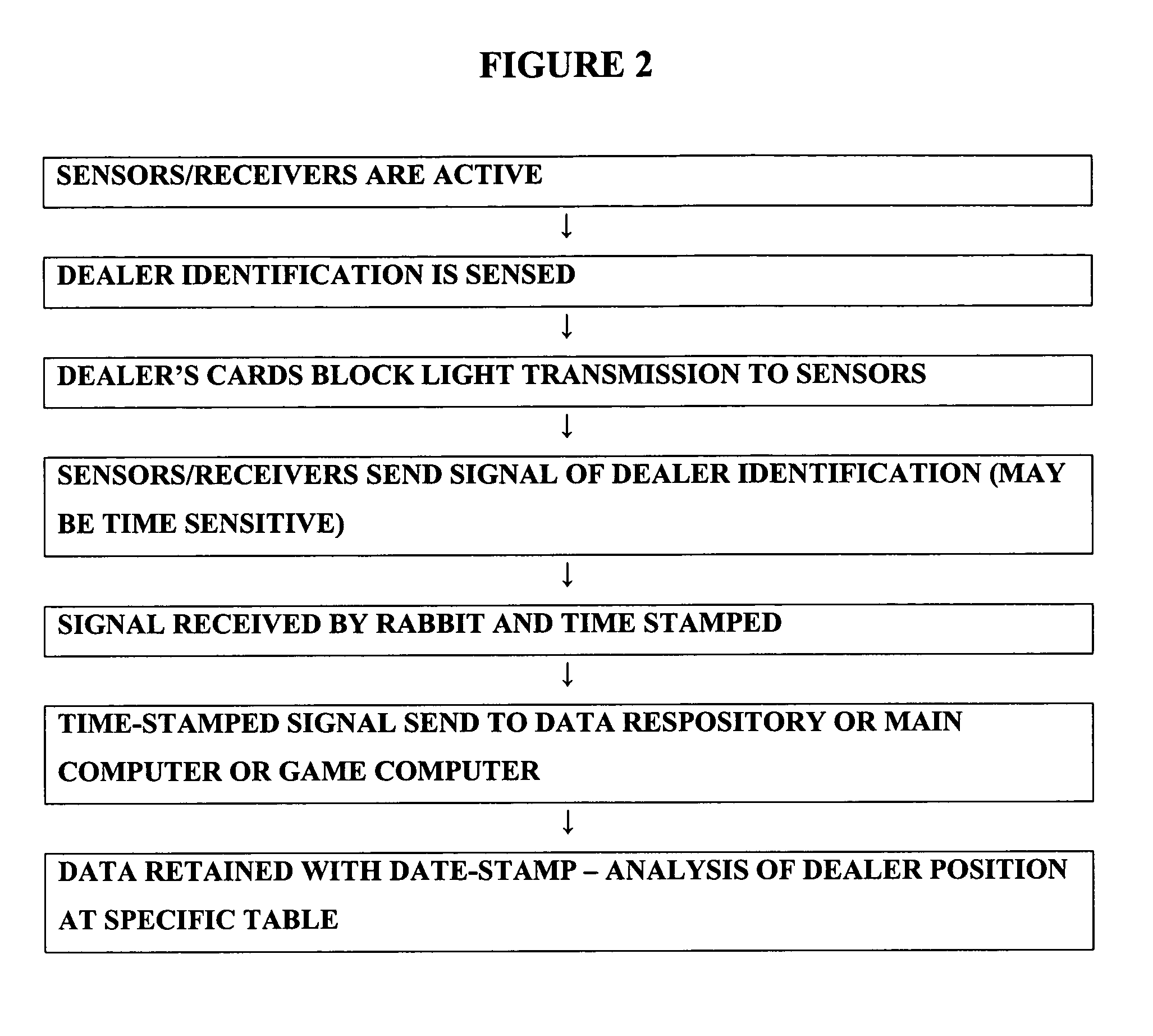
[0029] Casino table card games are provided with sensors or readers for detection of information or a signal identifying a crew member (e.g., dealer, croupier, pit worker, etc.) at a specific casino table. The table has a component that reads information or receives a first signal from the card. The first signal is received or read from a card (e.g., by swiping the card, or receiving an RF or responsive signal) by a table subcomponent that has a time or time/dating capability. The first signal is time/date stamped (referred to herein as “Date Stamping” or “date stamping” for simplicity) when sent, when read or when received. The date stamped signal is then transmitted from the subcomponent to a processor (e.g.,

Problems solved by technology

Processing equipment and computers have become an increasingly important part of the gaming industry, but the introduction of the technology has been sporadic, inconsistent, and often ill designed.
These casino table gaming devices and systems have been relatively simple and limited in scope, usually consisting of a few executing programs utilizing straight forward interrupt schemes and detection loops for asynchronous events for simple evaluation.

Method used


Image

  • Dealer identification system
  • Dealer identification system
  • Dealer identification system

Examples


Embodiment Construction

[0032] A casino table card gaming system communicates a message from a first subcomponent that receives casino employee identification information without date stamping. The casino employee identification information or data is transmitted to a first component that date stamps the signal. The first component forwards the date stamped signal to a memory component that stores the date stamped signal. The system comprises at least a casino table, a casino employee identification component, a casino employee identification data receiver that sends an undated signal, and the first component that receives the undated signal. The system may provide the data receiver as an employee identification card reader. The first component may, by way of non-limiting examples, comprise a chipboard, responsive electronics, broadcasting system, magnetic reader, optical reader / scanner, bar code reader, broadcast receiver, and the like. The first component need not have to store signals or data contained ...


PUM


Abstract

Casino table card games are provided with sensors or readers for detection of information or a signal identifying a crew member (e.g., dealer, croupier, pit worker, etc.) at a specific casino table. The table has a component that reads information or receives a first signal from the card. The first signal is received or read from a card (e.g., by swiping the card, or receiving an RF or responsive signal) by a table subcomponent that has a time or time / dating capability. The first signal is time / date stamped (referred to herein as “Date Stamping” or “date stamping” for simplicity) when sent, when read or when received. The date stamped signal is then transmitted from the subcomponent to a processor (e.g., gaming table processor or pit processor or main casino processor and / or central processor for multiple casinos). The data retains its date stamping at least through storage, analysis, data entry or other treatment of the data after transmission away from the table, and the date stamping may or may not be provided by the sensor / reader / receiver itself. The system also allows for the date stamping or other status information to be sent to a data bank or repository of information (e.g., security bank or security room) for storage of the information, without necessarily any game-play related function. The data may be processed in real time at this bank or repository, or may me reviewed and analyzed at a later time.

Description

RELATED APPLICATION DATA [0001] This application claims priority as a continuation-in-part of U.S. patent application Ser. No. 10 / 880,410, filed on Jun. 28, 2004 entitled APPARATUS FOR COUNTING ROUNDS OF PLAY IN A LIVE GAME OF CHANCE.BACKGROUND OF THE INVENTION [0002] 1. Field of the Invention [0003] The present invention relates to the field of casino table games, casino table games with live dealers, and casinos where monitoring of play and employee performance is desired. [0004] 2. Background of the Art [0005] Processing equipment and computers have become an increasingly important part of the gaming industry, but the introduction of the technology has been sporadic, inconsistent, and often ill designed. In addition, the direction of improvement in the processing apparatus used in casinos has consistently been heading in the direction that bigger and more powerful is better, attempting to mimic the home computer market. The original processors introduced into the market were hard...

Claims


Application Information

Patent Timeline
IPC IPC(8): A63F1/18A63F3/00A63F9/24G06F17/00G06F19/00G07F17/32
CPCA63F1/18A63F3/00157G07F17/3211G07F17/3206G07F17/32
Inventor SCHUBERT, OLIVER M.DOWNS, JUSTIN G. III
Owner SHUFFLE MASTER
Learn More