Combustion chamber design with water injection for direct-fired steam generator and for being cooled by the water

a combustion chamber and steam generator technology, applied in the direction of steam generation using hot heat carriers, machines/engines, lighting and heating apparatus, etc., can solve the problems of insufficient cooling of the bottom wall, which contains a centrally located exit outlet, and the solution is somewhat costly

Inactive Publication Date: 2006-01-05
DEERE & CO
View PDF11 Cites 8 Cited by
  • Summary
  • Abstract
  • Description
  • Claims
  • Application Information

AI Technical Summary

Benefits of technology

[0008] According to the present invention, there is provided an improved steam generator wherein the exterior surfaces

Problems solved by technology

While the patented structure includes a water jacket for cooling the length of the combustion chamber, the bottom wall, which contains a centrally located exit outlet for conveying steam and hot combustion gases, is not adequately cooled.
However, this solution is somewhat costly.
This water flow serves the purposes of providing secondary cooling to the combustion chamber, and of introducing water into the hot products of combustion so that it changes to steam while preventing water from coming in direct contact with the flame, such direct contact being undesirable since it would negatively affect combustion.
While this may be a suitable way to introduce feed water into a static combustion chamber, it has been found that in a mobile application, such as when the steam generator is being used to generate steam to re-hydrate crop just before baling, for example, the terrain traversed by the generator carrying vehicle may result in the combustion chamber becoming tilted, which causes an uneven flow of feed water along the inner wall of the combustion chamber.
The result of uneven flow is that a portion of the water prematurely flashed to steam in the combustion chamber.
As water flashes to steam, the water leaves behind solid particles (mineral deposits) on the combustion chamber walls and the steam disrupts the flame.
The mineral deposits build up over time and w

Method used


Image

  • Combustion chamber design with water injection for direct-fired steam generator and for being cooled by the water
  • Combustion chamber design with water injection for direct-fired steam generator and for being cooled by the water
  • Combustion chamber design with water injection for direct-fired steam generator and for being cooled by the water

Examples


Embodiment Construction

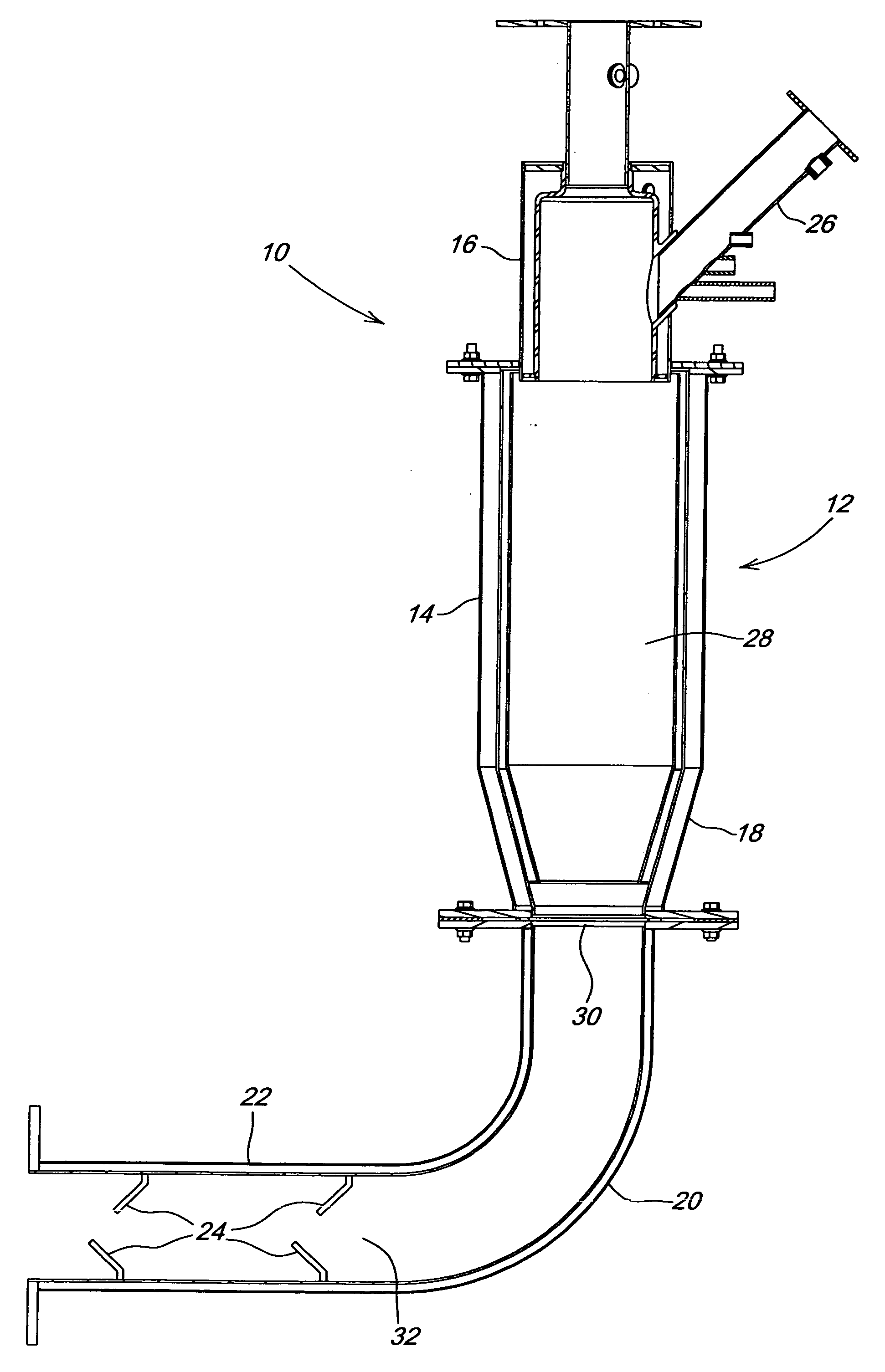
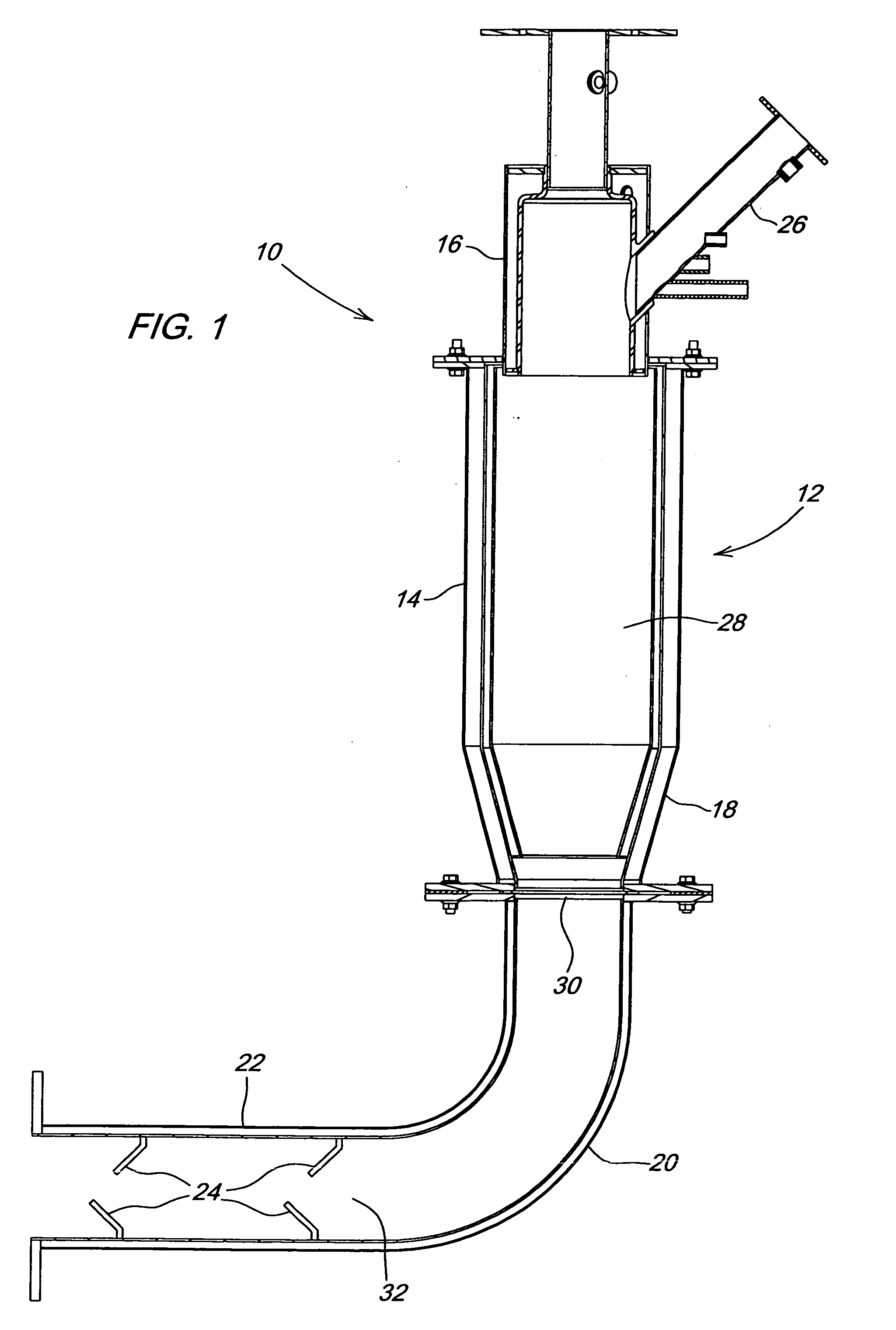
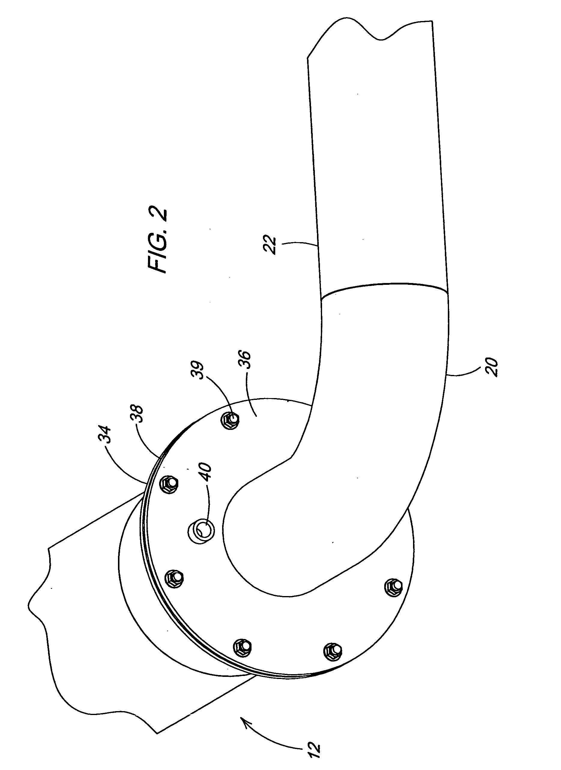
[0022] Referring now to FIG. 1, there is shown a portion of a direct-fired steam generator 10 including a steam generator body 12 having a relatively long cylindrical inlet section 14 to which a cylindrical burner head 16 is coupled, and having a relatively short conical outlet section 18. An elbow 20 is coupled between the outlet section 18 of the body 12 and a tubular static mixer 22 containing mixing fins or baffles 24 having a purpose explained in more detail below.

[0023] The burner head 16 includes a pilot burner tube 26 located such that it communicates with a lower region of the burner head 16. An igniter (not shown) is mounted so as to terminate within a lower region of the pilot burner tube 26. The igniter may be a spark plug or other type of sparking device, which operates to selectively ignite a fuel / air mixture selectively metered into an upper end of the pilot burner tube 26. When this mixture is ignited, it in turn acts to ignite a fuel / air mixture metered into an upp...


PUM


Abstract

A direct-fired steam generator body defines a combustion chamber and having an exhaust outlet. A mixing chamber is provided for receiving the exhaust gases from the combustion chamber. A flange joint between an elbow forming part of the mixing chamber and the end of the steam generator body defining the exhaust outlet is designed so as to be cooled by process water coupled to the joint by an injection port provided in one of the flanges.

Description

RELATED APPLICATION [0001] This is a continuation-in-part of application Ser. No. 10 / 883,865 filed, 02 Jul., 2004.FIELD OF THE INVENTION [0002] The present invention relates to direct-fired steam generators, and more specifically relates to a way of cooling, and of metering process water into the hot combustion gases at, an exhaust end of the combustion chamber. BACKGROUND OF THE INVENTION [0003] A direct-fired steam generator usually comprises a system formed from three parts, namely, a burner head, a combustion chamber, and a straight, or elbow-forming, tubular mixing chamber. Except for the mixing chamber, U.S. Pat. No. 4,211,071 discloses such a steam generator. Considerable heat is generated in the burner head, combustion chamber and mixing chamber [0004] While the patented structure includes a water jacket for cooling the length of the combustion chamber, the bottom wall, which contains a centrally located exit outlet for conveying steam and hot combustion gases, is not adequa...

Claims


Application Information

Patent Timeline
IPC IPC(8): F22G7/00F22B1/18F22B1/26
CPCF22B1/26F22B1/1853
Inventor KRAUS, TIMOTHY JAMESLANG, ERIC RYANSCHLESSER, WALTER MARK
Owner DEERE & CO
Why Eureka
Try Eureka