
High capacity purification of thermally unstable compounds

Inactive Publication Date: 2006-01-05
ROHM & HAAS CO
View PDF41 Cites 18 Cited by
  • Summary
  • Abstract
  • Description
  • Claims
  • Application Information

AI Technical Summary

Benefits of technology

[0010] The present invention can be achieved though retrofitting an existing distillation column by replacing at least two trays in the stripping section with a single tray capable of producing a tray pressure drop during the operation of the apparatus in the range of about 4 mmHg (0.08 psi) to about 6 mmHg (0.12 psi).
[0012] The present invention may have a distillation column with a wall having an internal surface defined by the internal column diameter wherein the open areas allow vapor to flow through at a sufficient velocity to entrain a liquid present on the surface of at least one stripping tray providing liquid mass transfer such that the liquid contacts with the internal surface so as to wet the internal surface.
[0013] The present invention includes another embodiment having sufficient trays to provide 8 or more theoretical stages of separation, wherein the rectification section has sufficient rectification trays to provide at least 4 theoretical stages of separation and the stripping section has sufficient trays to provide at least 4 theoretical stages of separation.
[0014] Any of the embodiments of the present invention may be utilized to purify reactive and / or thermally unstable compounds. The present invention may produce an overhead stream having an acrylic acid composition of less than 10 wt %.

Problems solved by technology

The known distillation columns (column(s)) commonly employed in the separation of thermally unstable and reactive compounds experience hydraulic instability, oscillation and unpredictable behavior.
These columns and trays experience polymer deposition, fluid bypassing, poor hydraulics, poor mixing, flow channeling and flow maldistribution, liquid weeping and poor liquid-vapor interaction.
Any one, or a combination, of these factors can result in reduced tray efficiencies and poor column performance.
The presence of polymer in separations processes is a significant problem.
Maintenance and personnel costs are burdensome and run times are short.
In traditional distillation processes for thermally sensitive materials, high temperatures and / or high per tray pressure drops have been determined to increase unwanted polymerization and create production difficulties including loss of efficiency, reduced capacity, damage to equipment, high maintenance and increased energy costs.
Inhibitors can be employed to reduce polymerization, however the cost of inhibitors is significant and reduces product purity.
Such approaches are burdensome to operate and expensive to build.
The aforementioned hydraulic and polymer based problems lower tray and column efficiency and prevent separations processes from meeting purity specifications.
They also create process control difficulties, result in unreliable sensor data and prevent accurate process simulation.
The purification processes utilized by manufacturers of acrylic acid (an industrially important compound which is reactive and thermally unstable) experience problems including, but not limited, to those set forth above when production capacity is high.

Method used


Image

  • High capacity purification of thermally unstable compounds
  • High capacity purification of thermally unstable compounds
  • High capacity purification of thermally unstable compounds

Examples


example 1

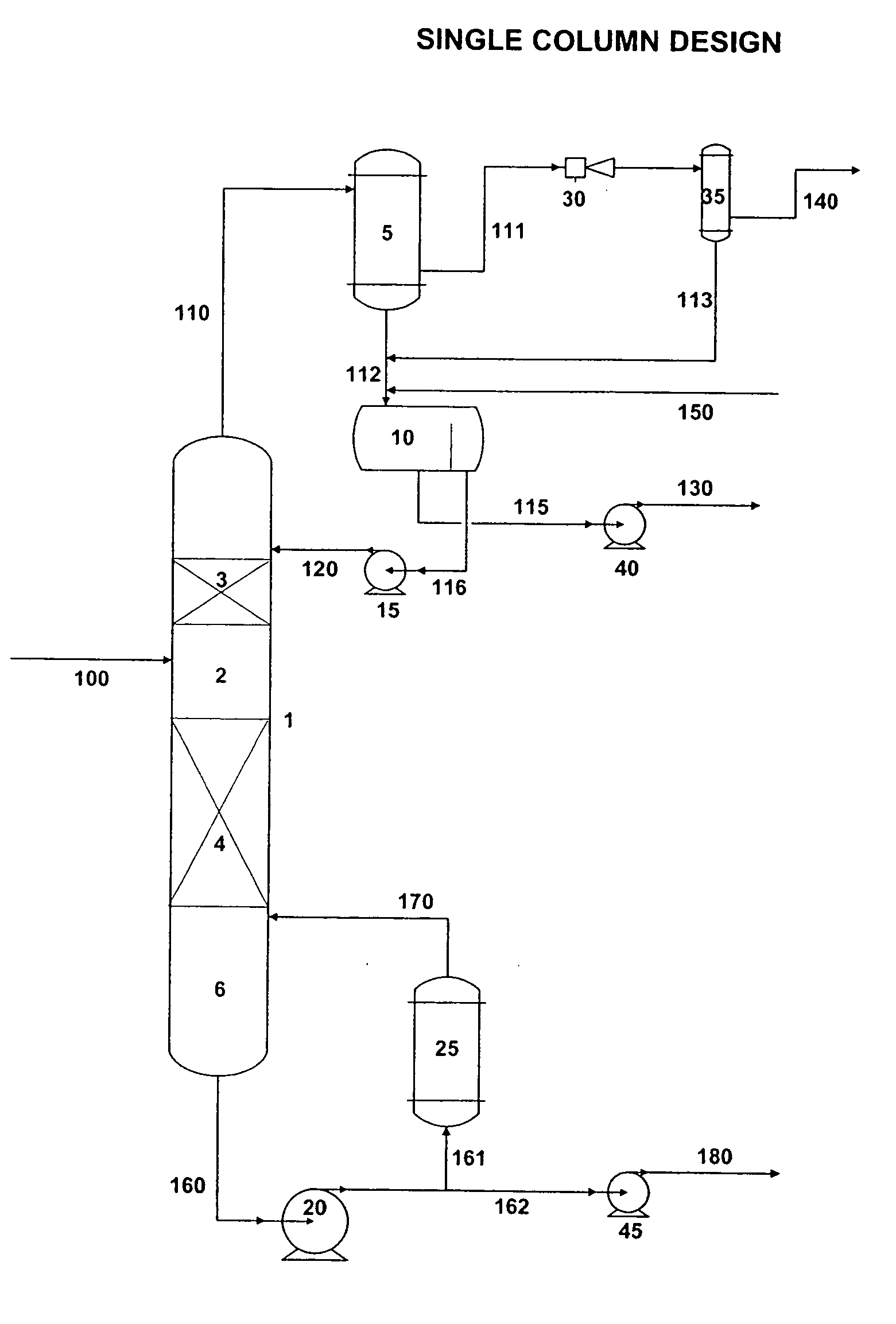
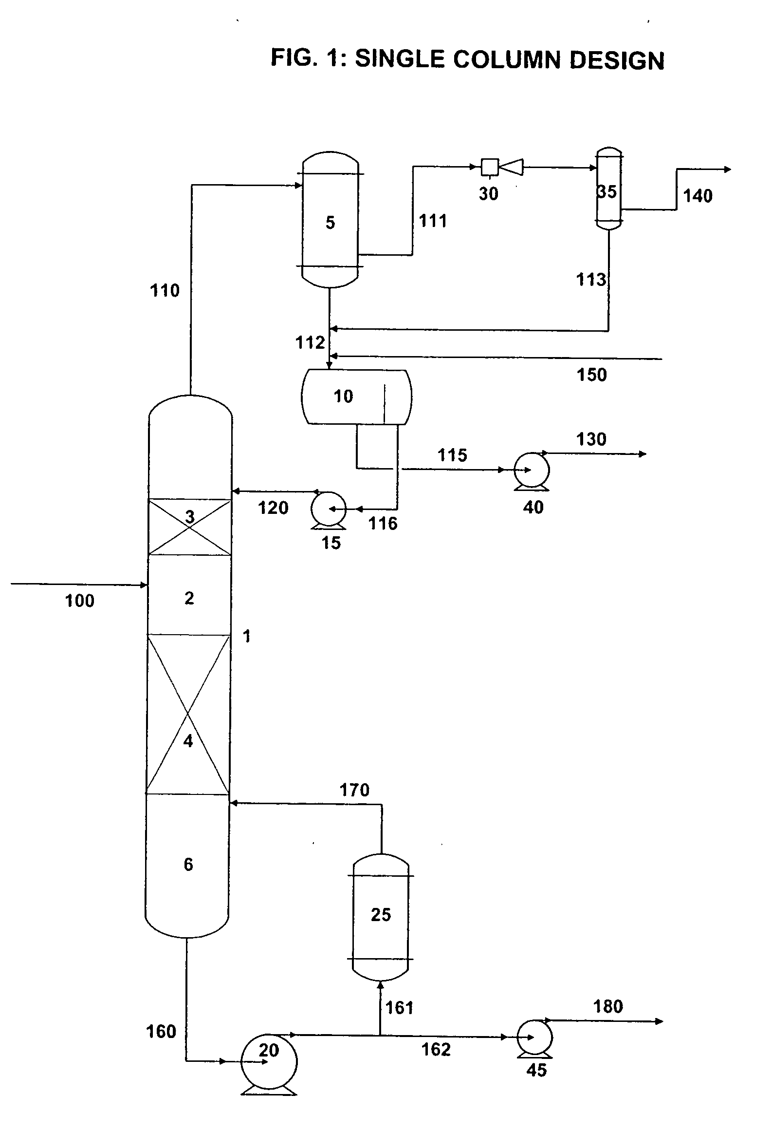
[0113] Acrylic acid was produced in accordance with the process diagram illustrated in FIG. 1. With reference to FIG. 1, acrylic acid-containing aqueous feed solution (100), azeotropic distillation column (1), azeotropic distillation column overhead vapor (110), condenser (5), aqueous-organic separator (10), azeotropic solvent containing reflux phase (120), aqueous containing distillate phase (130), azeotropic dehydration column bottoms (180).

[0114] Azeotropic distillation column (1), had the following physical characteristics:

[0115] 1. 172 in. ID column

[0116] 2. 71 dual-flow trays

[0117] 3. Lower trays had 24% open area

[0118] 4. Upper trays had 20% open area

[0119] Acrylic acid-containing aqueous feed solution (63-67 wt % acrylic acid, 2-4 wt % acetic acid, 1-3 wt % impurities, and 26-34 wt % water) was fed to column (1). Overhead pressure in column (1) was set to 110 mmHg (2.1 psi) absolute and total pressure drop through the trays was held to 120 mmHg (2.3 psi) to minimize bo...

example 2

[0121] Azeotropic distillation column (1) had the following physical characteristics:

[0122] 1. 172 in. ID column

[0123] 2. 54 dual-flow trays

[0124] 3. Lower trays had 16-18% open area

[0125] 4. Upper trays had 14-20% open area

[0126] Acrylic acid-containing aqueous feed solution (63-67 wt % acrylic acid, 2-4 wt % acetic acid, 1-3 wt % impurities, and 26-34 wt % water) was fed to column (1). Overhead pressure in column (1) was set to 110 mmHg (2.1 psi) and total pressure drop through the trays was allowed to rise to 140 mmHg (2.7 psi) resulting in a bottoms temperature of 111° C. (232° F.). Pressure drop per tray was increased to 4-6 mmHg (0.08-0.12 psi) by installing a plurality of lower open area trays in column (1).

[0127] Bottoms product (180) contained: 94-96 wt % acrylic acid, 4-6 wt % acrylic acid dimer, and 0.05-0.1 wt % acetic acid. Aqueous distillate product (130) contained: 1-2 wt % acrylic acid, 6-8 wt % acetic acid, and 90-93 wt % water. Tray efficiencies for the 16-18...

example 3

[0128] An existing acrylic acid column was retrofit (modified, revamped, retrofitted) to achieve a first retrofit embodiment and a second retrofit embodiment of the present invention. The “after retrofitting” column of table 5 contains the data of the Second Retrofit Embodiment. The operating data from before and after modification is found in the table below.

[0129] Column trays in this example are of the dual flow type. The initial modifications recently in the first retrofit embodiment were as follows: trays 3, 5, 7, 9, 11, 13, 15, 17, 19, 21, 23, 25, and 27 removed (71 original total trays). Installed 16.24% hole area tray panels (w / ½″ ID holes) on trays 2, 4, 6, 8, 10, 12, 14, 16, 18, 20, 22, and 24. Installed 20.00% hole area tray panel (w / ½″ ID holes) on tray 26.

[0130] The final modifications resulting in the second retrofit embodiment were as follows: Removed 16.24% hole area tray panels (w / ½″ ID holes) on trays 14, 16, 18, 20, 22, and 24 (72 original total trays). Installe...


PUM

PropertyMeasurementUnit
Lengthaaaaaaaaaa
Pressureaaaaaaaaaa
Pressureaaaaaaaaaa

Abstract

Separations processes and apparati capable of purifying thermally sensitive materials at high capacity. An apparatus having a rectification section and a stripping section with the stripping section having a stripping tray with 5 to 50% open area, a pressure drop from 0.02 psi to 0.2 psi and a tray efficiency during operation of the column which is equal to or greater than 20%.

Description

FIELD OF THE INVENTION [0001] This invention is related to the methods and apparati for the high capacity purification of thermally sensitive, unstable, or reactive compounds. BACKGROUND OF THE INVENTION [0002] The purification of thennally sensitive, unstable, or reactive compounds such as acrylic acid is typically attempted by continuous vacuum distillation or other vapor-liquid separation processes utilizing low pressure drop trays. [0003] The known distillation columns (column(s)) commonly employed in the separation of thermally unstable and reactive compounds experience hydraulic instability, oscillation and unpredictable behavior. Column trays run dry or have dry spots. These columns and trays experience polymer deposition, fluid bypassing, poor hydraulics, poor mixing, flow channeling and flow maldistribution, liquid weeping and poor liquid-vapor interaction. Any one, or a combination, of these factors can result in reduced tray efficiencies and poor column performance. [0004...

Claims


Application Information

Patent Timeline
IPC IPC(8): B01D3/14C07C51/42B01D3/16B01D3/22B01D3/32C07C51/44C07C57/07
CPCB01D3/166B01D3/22B01D3/225Y10S203/22C07C51/44C07C57/04
Inventor MASON, ROBERT MICHAELGOODWIN, JEFFERY ALANMYERS, RONALD DREWDECOURCY, MICHAEL STANLEY
Owner ROHM & HAAS CO
Learn More