Drive method for piezoelectric actuator, drive apparatus for piezoelectric actuator, electronic device, control program for drive apparatus for piezoelectric actuator, and recording medium

Inactive Publication Date: 2006-01-05
SEIKO EPSON CORP
View PDF11 Cites 9 Cited by
  • Summary
  • Abstract
  • Description
  • Claims
  • Application Information

AI Technical Summary

Benefits of technology

[0015] A first object of the present invention is to provide a drive method for a piezoelectric actuator, a drive apparatus for a piezoelectric actuator, an electronic device having this piezoelectric actuator, a control program for the drive device of a piezoelectric actuator, and a recording medium on which this control program is recorded, wherein the piezoelectric actuator can be reliably driven, the power consumption can be reduced, and nonuniformities in the speed at which the driven object is driven by the piezoelectric actuator can be reduced. In addition to the first object, a second object of the present invention is to provide a drive method for a piezoelectric actuator, a drive apparatus for a piezoelectric actuator, an electronic device having this piezoelectric actuator, a control program for the drive device of a piezoelectric actuator, and a recording medium on which this control program is recorded, wherein the driven object can be driven at a 
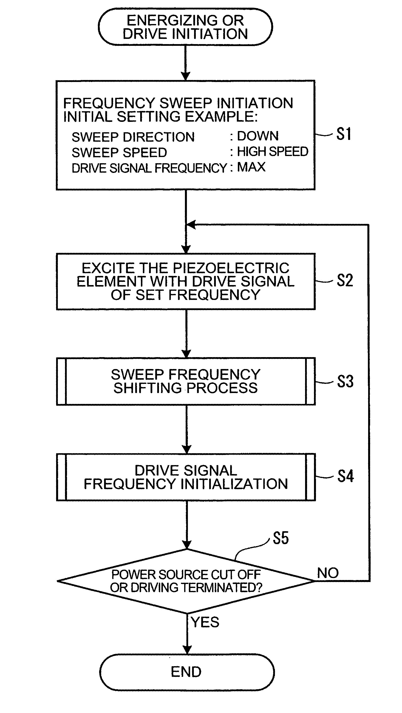
specific speed, control can be simplified, and cost increases can be suppressed, even when nonuniformities occur in the characteristics of the piezoelectric actuator. A drive method for a piezoelectric actuator according to a first aspect of the present invention use a piezoelectric actuator having a vibrating body that is vibrated by the application of a drive signal with a specific frequency to a piezoelectric element, and a contact section provided on the vibrating body and pressed against the driven object. Further, the frequency of the drive signal supplied to the piezoelectric element is swept within a specific range, a detection signal indicating the vibrating state of the vibrating body is detected, and the speed at which the frequency of the drive signal supplied to the piezoelectric element is swept is controlled based on this detection signal. In this aspect of the present invention, since the frequency of the drive signal is varied or swept within a specific range, the piezoelectric element can be reliably driven as long as the element is driven within this frequency range. Also, since the drive signal is constantly swept within a specific frequency range, the drive frequency of the piezoelectric element may be nonuniform due to fluctuations in the surrounding temperature, noise, and load, but it is possible to overcome such nonuniformities without making adjustments. Therefore, there is no need to provide the drive apparatus with a determination circuit for determining fluctuations in the surrounding temperature, noise, and load, or an adjustment circuit for adjusting the frequency of the drive signal on the basis of such determination data, and the configuration of the drive apparatus can be simplified.
[0016] Furthermore, since the sweep speed of the drive signal frequency is controlled based on the detection signal that indicates the vibrating state of the vibrating body, the speed at which the drive signal is swept can be increased when the amount by which the vibrating body vibrates is small and the driven object is at rest, and the speed can be reduced when the amount by which the vibrating body vibrates is large and the driven object is in a drive state. Needless drive signal output time during which the driven object cannot be driven can thereby be shortened, needless power consumption can be curtailed, and efficiency can be improved. Further, since the non-drive state can be shortened, nonuniformities over a specific drive time (for example, 1 minute) can be reduced, discrepancies (nonuniformities) in the speed at which the driven object (driven member) is driven by the vibrating body can be reduced, and high-speed driving can be achieved, even with fluctuations in the load and the like.

Problems solved by technology

Therefore, since the drive signal output from the voltage control oscillator continues even in frequency ranges in which the piezoelectric vibrating element is not driven, unnecessary power consumption occurs.
Specifically, the drive speed and driving efficiency cannot be improved.
Further, in piezoelectric actuators, individual differences and characteristic differences occur as a result of nonuniformities in manufacturing the piezoelectric element, as well as nonuniformities in the angle of contact between the piezoelectric element and the driven object, the contact pressure, and the like.
Therefore, as described in Prior Art 1, when the oscillation frequency is swept, problems are encountered with the occurrence of nonuniformities in the speed at which the driven object is driven by the piezoelectric actuator, for example, in the rotating speed of the rotor when a rotor is rotatably driven, as a result of individual differences and the like in the piezoelectric actuator.
Problems with the occurrence of nonuniformities in the drive speed are also encountered when the piezoelectric actuator degrades.
It is also necessary that the driving of the piezoelectric actuator is feedback-controlled on the basis of this information, which leads to problems of complicating the control and increasing costs.

Method used


Image

  • Drive method for piezoelectric actuator, drive apparatus for piezoelectric actuator, electronic device, control program for drive apparatus for piezoelectric actuator, and recording medium
  • Drive method for piezoelectric actuator, drive apparatus for piezoelectric actuator, electronic device, control program for drive apparatus for piezoelectric actuator, and recording medium
  • Drive method for piezoelectric actuator, drive apparatus for piezoelectric actuator, electronic device, control program for drive apparatus for piezoelectric actuator, and recording medium

Examples


second embodiment

[0161] A second embodiment will now be explained. In view of the similarity between the first and second embodiments, the parts of the second embodiment that are identical to the parts of the first embodiment will be given the same reference numerals as the parts of the first embodiment. Moreover, the descriptions of the parts of the second embodiment that are identical to the parts of the first embodiment may be omitted for the sake of brevity.

[0162] Next, the configuration of the drive apparatus 50A for the piezoelectric actuator 91 in accordance with a second preferred embodiment of the present invention will be described with reference to FIGS. 9 and 10.

[0163] In FIG. 9, the drive apparatus 50A has a drive circuit 55 to output a drive signal to the piezoelectric element 912 of the piezoelectric actuator 91, and a frequency control device 51 to control the frequency of the drive signal outputted from the drive circuit 55.

[0164] The frequency control device 51 is configured fro...


PUM


Abstract

A frequency of a drive signal supplied to a piezoelectric element is swept within a specific range, a detection signal indicating the vibrating state of a vibrating member is detected, and the sweep speed of the drive signal frequency supplied to the piezoelectric element is controlled based on this detection signal. Thus, even if nonuniformities occur in the drive frequency of the piezoelectric element due to fluctuations in the surrounding temperature or the load, such nonuniformities can be overcome without any adjustments, and the piezoelectric element can be reliably driven. Also, since the sweep speed of the drive signal frequency is at a high speed when the vibrating member is in a non-drive state, needless drive signal output time during which the piezoelectric element cannot be driven can be reduced, needless power consumption can be curtailed, and nonuniformities in the drive speed of the driven object can also be reduced.

Description

CROSS-REFERENCE TO RELATED APPLICATIONS [0001] This application claims priority to Japanese Patent Application No. 2004-196741 and 2004-215905. The entire disclosure of Japanese Patent Application No. 2004-196741 and 2004-215905 are hereby incorporated herein by references. BACKGROUND OF THE INVENTION [0002] 1. Field of the Invention [0003] The present invention generally relates to a drive method for a piezoelectric actuator. More specifically, the present invention relates to a drive method for a piezoelectric actuator, a drive apparatus for a piezoelectric actuator, an electronic device, a control program for the drive device of a piezoelectric actuator, and a recording medium. [0004] 2. Background Information [0005] Piezoelectric elements have an excellent conversion ratio of electrical energy to mechanical energy, and also have excellent responsiveness. Various piezoelectric actuators that utilize the piezoelectric effects of piezoelectric elements have therefore been recently ...

Claims


Application Information

Patent Timeline
IPC IPC(8): H01L41/04
CPCH02N2/004H02N2/142H02N2/101H02N2/103
Inventor MATSUZAKI, JUNKAWAGUCHI, TAKASHINAGAHAMA, REIKO
Owner SEIKO EPSON CORP
Why Eureka
Try Eureka