Magnetic actuator trip and close circuit and related methods

Inactive Publication Date: 2006-01-05
SCHWEITZER ENGINEERING LABORATORIES
View PDF10 Cites 10 Cited by
  • Summary
  • Abstract
  • Description
  • Claims
  • Application Information

AI Technical Summary

Benefits of technology

[0013] This invention is directed to circuitry for controlling the flow of current through an actuator coil of a recloser to selectively open or close electrical contacts of the recloser depending upon the direction of current flow through the actuator coil. The circuitry includes a source of DC voltage, a capacitor that is charged from the source of DC voltage, a first pair of transistors connected in series with the actuator coil to apply the charge from the capacitor to the actuator coil with a polarity that will energize the actuator coil to close the electrical contacts of the recloser when the first pair of transistors is rendered conductive, a first pair of diodes, one of each of the first pair of diodes in parallel with one of a second pair of transistors and poled to conduct current from

Problems solved by technology

If an over-current or fault condition occurs, the recloser may open its electrical contacts at a known time delay after the occurrence of the over-current or fault condition.
However, if the over-current or fault condition persists, the recloser will typically go to a lock-out condition after failing to successfully reclose after about three attempts.
In this situation, the contacts of the DPDT relay may be damaged if the DPDT relay is switched to the opposite position to open or trip the reclose

Method used


Image

  • Magnetic actuator trip and close circuit and related methods
  • Magnetic actuator trip and close circuit and related methods

Examples


Example

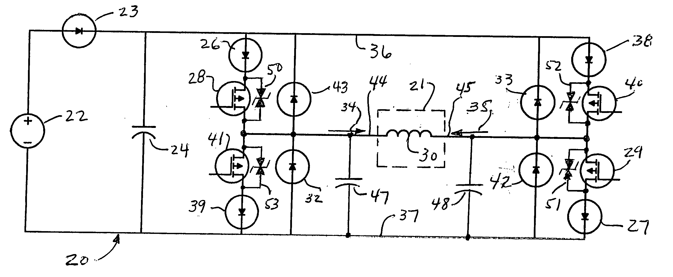
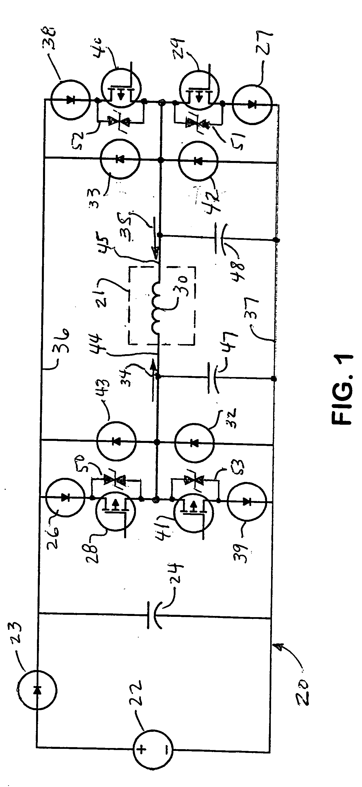
[0021] An electronic circuit, generally designated 20, for controlling the magnetic actuator of a recloser 21 in accordance with the present invention is shown in FIG. 1. The magnetic actuator includes an actuator coil 30 which is selectively energized by circuit 20 to open or close electrical contacts (not shown) in the recloser 21 in a manner known in the art, depending upon the direction of current through the actuator coil. Typically, recloser 21, including actuator coil 30, is located in a box at an elevated position on a utility pole or transmission tower, such as near or adjacent to the transmission lines of an electrical distribution system. On the other hand, circuit 20 is typically located close to ground level, with a pair of lines 44 and 45 providing electrical connection from circuit 20 to actuator coil 30. The length of lines 44-45 between actuator coil 30 and circuit 20 is thus exposed to the air and to ambient conditions associated with the electrical distribution sy...


PUM


Abstract

A circuit for a recloser controls the flow of current through an actuator coil to selectively open or close the electrical contacts of the recloser. The circuit utilizes pairs of transistors and pairs of diodes to apply the charge on a capacitor to open or close the contacts and to recharge the capacitor when the contacts open or close. The potential on the capacitor opposes current flow through the actuator coil for rapid decay of the actuator coil current, which also enables a rapid opening of the contacts after closure into a high current fault or the like. The capacitor also protects the transistors from voltage transients. Related methods are also presented.

Description

FIELD OF THE INVENTION [0001] The present invention relates generally to electrical distribution systems. More particularly, the invention relates to apparatus and methods for tripping or closing of reclosers in electrical distribution systems. BACKGROUND OF THE INVENTION [0002] Reclosers are sometimes referred to as auto-reclosers, auto-reclosing circuit breakers, reclosing relays, or the like. Reclosers have electrical contacts that close or open power lines in high voltage electrical distribution systems to provide electrical power to the power lines in the system. If an over-current or fault condition occurs, the recloser may open its electrical contacts at a known time delay after the occurrence of the over-current or fault condition. Actuation circuitry will sense any open condition of the recloser and one or more attempts will be made to reclose the electrical contacts of the recloser. However, if the over-current or fault condition persists, the recloser will typically go to...

Claims


Application Information

Patent Timeline
IPC IPC(8): H01H75/00
CPCH02H3/06H01H47/226
Inventor MINTEER, TIMOTHY M.
Owner SCHWEITZER ENGINEERING LABORATORIES
Why Eureka
Try Eureka