Liquid crystal display

Inactive Publication Date: 2006-01-05
SONY CORP
View PDF5 Cites 41 Cited by
  • Summary
  • Abstract
  • Description
  • Claims
  • Application Information

AI Technical Summary

Benefits of technology

[0014] With this structure, the light-shielding means blocks the light from the light source of the LCD projector and prevents light from the li

Problems solved by technology

The increase in temperature of the driver ICs may result in driver malfunction, degraded image quality resu

Method used


Image

  • Liquid crystal display
  • Liquid crystal display
  • Liquid crystal display

Examples


first embodiment

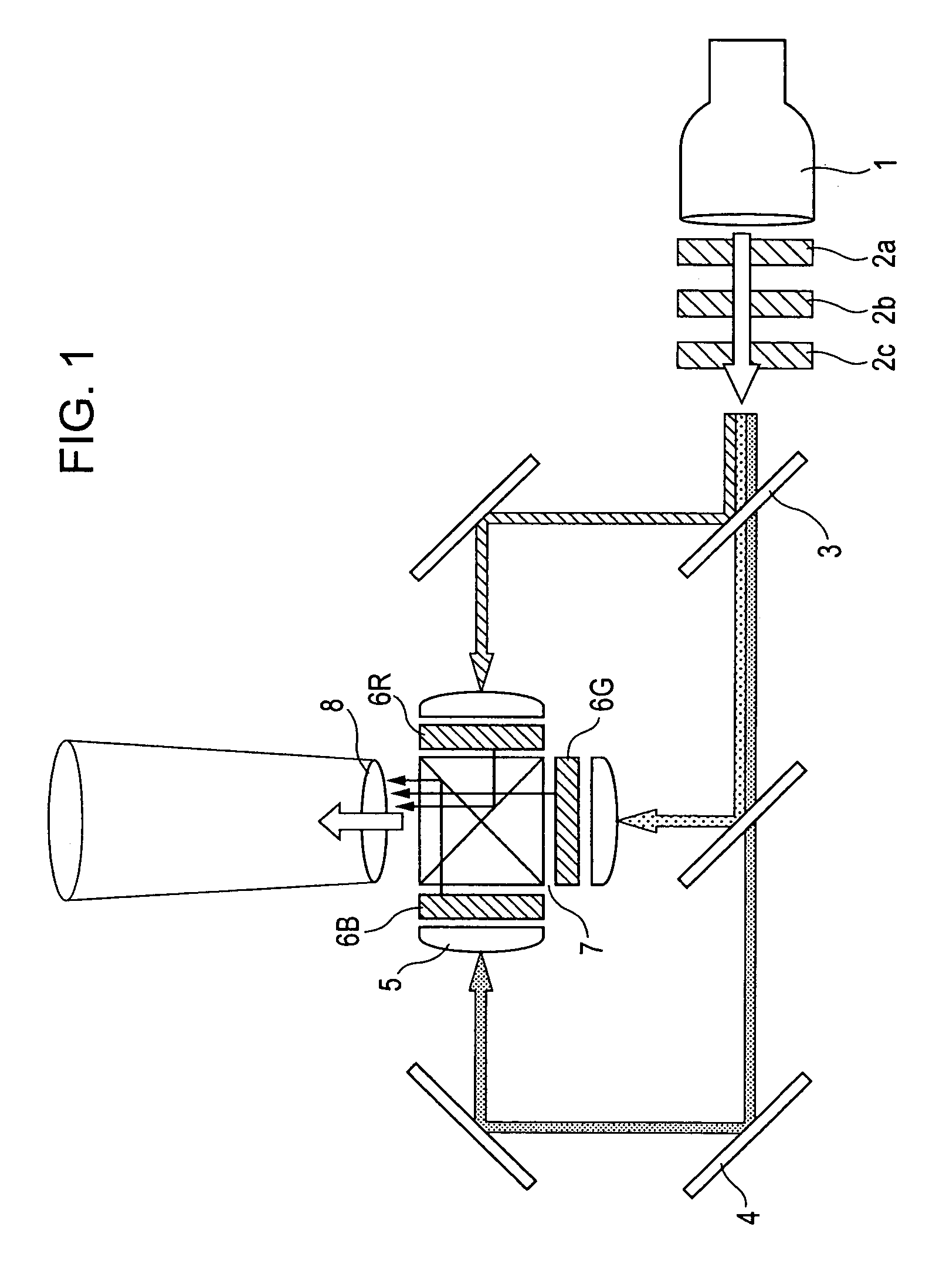
[0037] A LCD projector incorporating liquid crystal displays is first described. A three-panel liquid crystal display (LCD) projector that includes three liquid crystal displays respectively having panels of red, green, and blue is widely known. FIG. 1 is a diagram showing the configuration of a three-panel LCD projector.

[0038] Referring to FIG. 1, light emitted from a light source 1 passes through a filter 2a that cuts infrared and UV rays, a fly-eye lens 2b, and a PS splitter / synthesizer for converting unpolarized light to polarized light, and is split into R, G, and B light beams with dichroic mirrors 3 that each reflect only a light beam in a particular wavelength region. The RGB light beams respectively enter liquid crystal displays 6R, 6G, and 6B via total reflection mirrors 4 and a condenser lens 5 where necessary, and modulated according to image signals in the liquid crystal displays 6R, 6G, and 6B. The modulated light beams are combined with a dichroic prism 7 and enlarge...

second embodiment

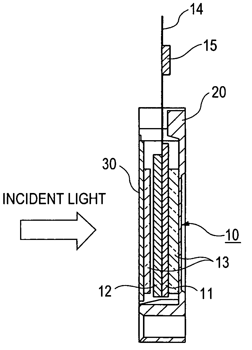
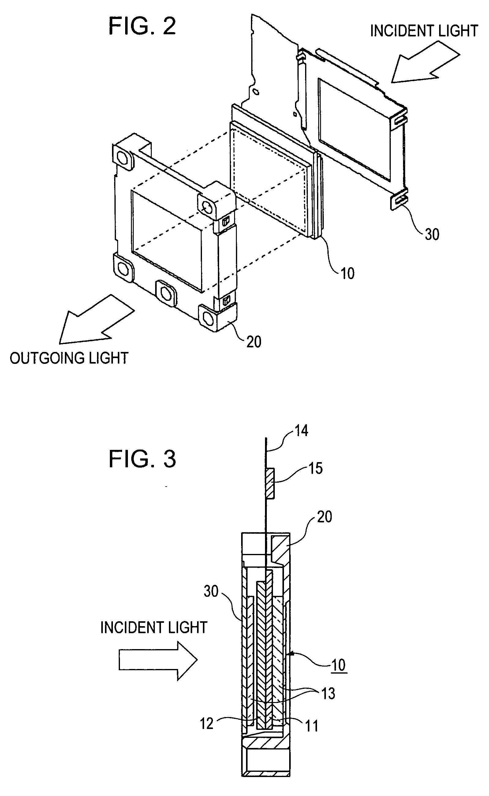
[0058] A liquid crystal display according to a second embodiment will now be described. The liquid crystal display of the second embodiment is shown in FIG. 10. The driving IC 15 is located distant from the outer edge of the support of the liquid crystal display panel 10, by a distance A in the outward direction.

[0059] The term “support” here refers to a component that supports the liquid crystal display panel 10. In particular, the frame 20 and the light-shielding panel 30 may each function as a support. Referring to FIG. 11, when the frame 20 is attached to a mounting board 40 so that the liquid crystal display can be attached to a dichroic prism (not shown), the mounting board 40 also function as a support. In this example, the driving IC 15 is located distant from the outer edge of the conductive pattern 40 by a distance B in the outward direction.

[0060] The phrase “distant from the outer edge of the support in the outward direction” means that the component is outside the reg...

third embodiment

[0074] A liquid crystal display of a third embodiment will now be described with reference to FIGS. 16A and 16B. The liquid crystal display includes the liquid crystal display panel 10, the frame 20, and the light-shielding panel 30. The frame 20 is disposed at the outgoing light-side of the liquid crystal display panel 10 and functions as a support of the liquid crystal display panel 10. The frame 20 may be composed of a metal material, such as aluminum, magnesium, stainless steel, having high heat conductivity, or a resin having high heat conductivity. The light-shielding panel 30 is disposed at the incident light-side of the liquid crystal display panel 10 and shields light entering the region outside the effective pixel region. The light-shielding panel 30 may be a metal or resin plate with high heat conductivity having an opening corresponding to the effective pixel region.

[0075] The detailed structure and the operation of the liquid crystal display panel 10 are the same as th...


PUM


Abstract

A liquid crystal display for use in a LCD projector includes a liquid crystal display panel including a TFT substrate, a counter substrate, and liquid crystal interposed between the TFT substrate and the counter substrate; a flexible film substrate being electrically coupled to the liquid crystal display panel and having a plurality of leads including at least one dummy lead; and a driving IC for driving the liquid crystal display panel, the driving IC being disposed on the film substrate and having at least one dummy bump. The dummy bump is connected to the dummy lead, and the dummy lead has a heat releasing function.

Description

CROSS REFERENCES TO RELATED APPLICATIONS [0001] The present invention contains subject matter related to Japanese Patent Application JP 2004-196217 filed in the Japanese Patent Office on Jul. 2, 2004, Japanese Patent Application JP 2004-196218 filed in the Japanese Patent Office on Jul. 2, 2004, and Japanese Patent Application JP 2004-197691 filed in the Japanese Patent Office on Jul. 5, 2004, the entire contents of which are incorporated herein by reference. BACKGROUND OF THE INVENTION [0002] 1. Field of the Invention [0003] The present invention relates to liquid crystal displays for use in liquid crystal display (LCD) projectors. [0004] 2. Description of the Related Art [0005] LCD projectors that operate by selectively transmitting light from a light source using liquid crystal displays and then throwing the transmitted light onto a screen to deliver images on large-screens have gained popularity in recent years. The liquid crystal displays incorporated in these LCD projectors ty...

Claims


Application Information

Patent Timeline
IPC IPC(8): G02F1/1345
CPCH04N9/3144G02F1/13452
Inventor DEWA, SHIGEKUNIFUNAKOSHI, SEIICHIYAMADA, MASASHI
Owner SONY CORP
Why Eureka
Try Eureka