Incandescent reflector heat lamp with uniform irradiance

a technology of incandescent reflectors and heat lamps, which is applied in the field of incandescent lamps, can solve the problems of inability to achieve a large area of uniform irradiance on a flat surface, the maximum bean spread is very limited, and the heat lamps currently available do not perform the desired function well

Inactive Publication Date: 2006-01-05
LEDVANCE LLC
View PDF12 Cites 3 Cited by
  • Summary
  • Abstract
  • Description
  • Claims
  • Application Information

AI Technical Summary

Benefits of technology

[0009] It is yet another object of the invention to provide an in

Problems solved by technology

However, presently available heat lamps usually do not perform the desired function well because the lamps have a non-uniform power distribution with maximum radiant intensity on axis dropping to 50% of peak within about 15 degrees of the lamp axis.
The BR40 and R-40 lamps realize some beam spread by use of a frosted inner surface so the maximum bean spread is very limited.
It is not possible to achieve a large area of uniform irradiance on a flat surface using conventional lens op

Method used


Image

  • Incandescent reflector heat lamp with uniform irradiance
  • Incandescent reflector heat lamp with uniform irradiance
  • Incandescent reflector heat lamp with uniform irradiance

Examples


Embodiment Construction

[0016] For a better understanding of the present invention, together with other and further objects, advantages and capabilities thereof, reference is made to the following disclosure and appended claims taken in conjunction with the above-described drawings.

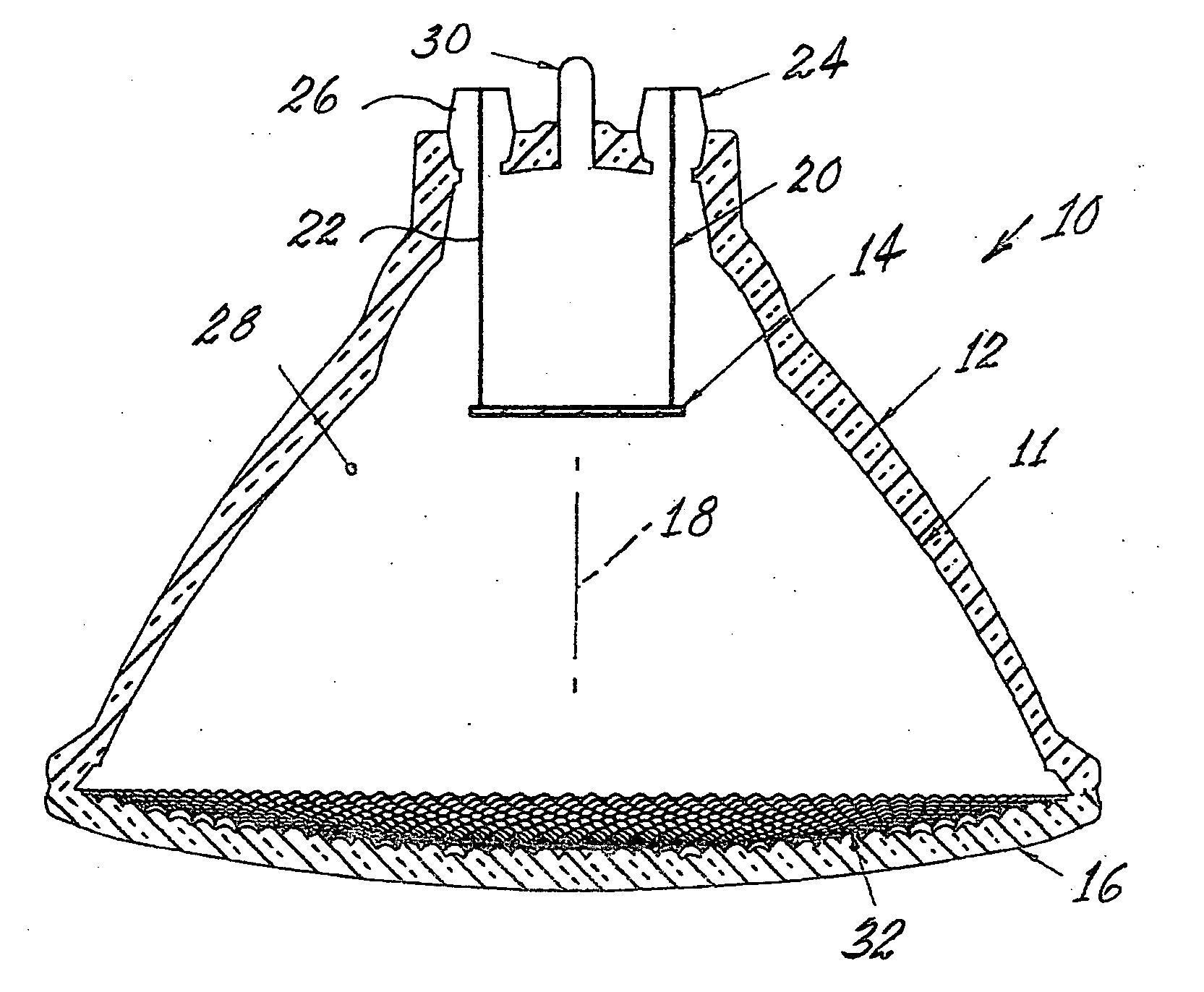
[0017] Referring now to the drawings with greater particularity, there is shown in FIG. 1 a cross-section of an embodiment of the invention comprising an infrared emitting heat lamp 10 having a body 12 sealed to a lens 16. At least a portion of the inner reflector part 11 of body 12 has a parabolic configuration. This inner reflector part 11 can be coated with aluminum or other reflective material. An infrared heat source, such as a tungsten coil 14 is positioned near the focal point of the parabolically shaped reflector part 11 so that a substantial portion of the radiated power has a direction parallel to the lamp axis 18. The radiating source 14 is supported by in-lead wires 20, 22, which are brazed or otherwise affixed to m...


PUM


Abstract

An infrared heat lamp has a reflector body closed by a lens and having a source of infrared radiation positioned within the body. The lens has a plurality of lenticules formed thereon to provide substantially uniform radiant intensity within a 50° cone on a planar surface spaced from the lens, the radiant intensity varying as the inverse of (cos β)2. In a preferred embodiment all of the lenticules have a parabolic shape.

Description

TECHNICAL FIELD [0001] This invention relates to incandescent lamps and more particularly to such lamps employed as radiant heat sources. BACKGROUND ART [0002] Directional infrared heat lamps are commonly available as BR40 or R-40 lamps having envelopes made from soft glass. Additionally, it is known to make such lamps in PAR38 format from pressed hard glass reflector and lens components. These lamps are often used in agricultural or industrial applications where it is desired that a relatively large flat surface must be uniformly heated. However, presently available heat lamps usually do not perform the desired function well because the lamps have a non-uniform power distribution with maximum radiant intensity on axis dropping to 50% of peak within about 15 degrees of the lamp axis. The radiant beam angle in such cases is about 30 degrees. [0003] The current models of such heat lamps have been based upon the standard lamps designed for general lighting purposes and use most of the ...

Claims


Application Information

Patent Timeline
IPC IPC(8): F21S6/00H05B3/00
CPCH05B2203/032H05B3/009F21V5/046
Inventor KLING, MICHAEL R.
Owner LEDVANCE LLC
Why Eureka
Try Eureka