Fluid management apparatus and method

a technology of flue gas management and flue gas, which is applied in the direction of fluorescence/phosphorescence, electric/magnetic/electromagnetic heating, instruments, etc., can solve the problems of oil thermal degradation, oil can become less effective at heat and debris transfer, and the effect of reducing the size, weight and cost of the apparatus

Inactive Publication Date: 2014-01-30
ROLLS ROYCE PLC
View PDF5 Cites 7 Cited by
  • Summary
  • Abstract
  • Description
  • Claims
  • Application Information

AI Technical Summary

Benefits of technology

[0019]The same laser or lasers may provide both the first and second pulses. The dual use of the laser may reduce the size, weight and cost of the apparatus.
[0020]The laser may be a continuous wave laser. The continuous wave laser may have a higher fluence than a pulsed laser. The high fluence of a continuous wave laser may allow heat to be supplied to the particulate matter at the same time as it is being lost to the surrounding gas. This may allow single particles to be detected as they pass through the continuous wave laser beam.

Problems solved by technology

However, high efficiency separators effectively eliminate oil consumption, which over time can cause the oil to thermally degrade, becoming acidic and leaving deposits around the oil system.
Furthermore, the oil can become less effective at performing its function of heat and debris transference.
Moreover, the oil / air mixture discharged overboard may have the appearance of smoke, particularly when the aircraft is stationary or moving relatively slowly.
This may cause distress to passengers as the smoke may be mistakenly assumed to be a problem with the engine.
Furthermore, the oil / air mixture may cause unsightly staining of the engine nacelle as it is discharged overboard and may also stain the runway surface.
However, whilst the breather outlet is able to reduce the appearance of smoke, it does not provide any quantitative information regarding the egress of oil from the engine.

Method used


Image

  • Fluid management apparatus and method
  • Fluid management apparatus and method

Examples


Embodiment Construction

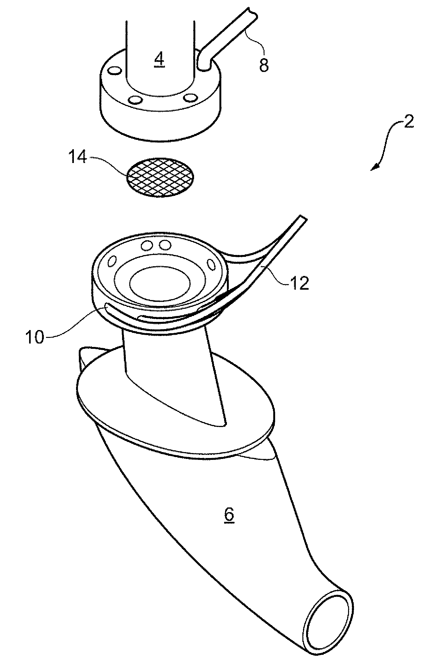
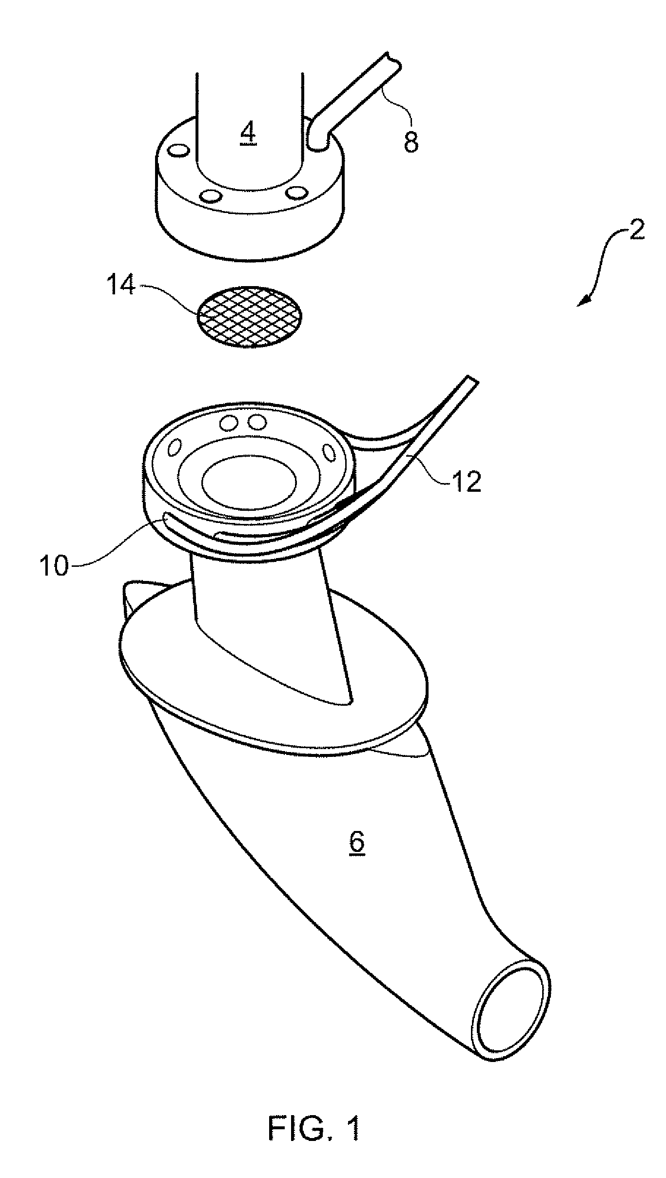
[0033]With reference to FIG. 1, a fluid management apparatus according to an embodiment of the invention comprises a breather outlet 2 for a gas turbine engine.

[0034]The gas turbine engine comprises an oil or lubrication system, as known in the art, which maintains a supply of oil to engine components, such as a bearing chamber (not shown). As discussed previously, the bearing chamber is held under a negative pressure to ensure oil does not undesirably escape from the chamber into the rest of the engine. To maintain the negative pressure, air is bled out of the bearing chamber. The air bled from the bearing chamber contains droplets of oil. This mixture of air and oil is passed to an oil / air separator, such as a centrifugal vane separator which rotates at high speed to separate the oil from the air. The separated oil is returned to the lubrication system while the air is discharged overboard via the breather outlet 2. The breather outlet 2 therefore provides fluid communication betw...


PUM

PropertyMeasurementUnit
diameteraaaaaaaaaa
timeaaaaaaaaaa
timeaaaaaaaaaa

Abstract

A fluid management apparatus and method, the apparatus including: a fluid conduit for the passage of a dispersion containing particulate matter; a laser arranged to provide laser light inside the fluid conduit; wherein, in use, the laser light heats the particulate matter sufficiently to generate incandescence; one or more sensors for detecting the incandescence of the particulate matter so as to determine a characteristic of the dispersion; and an electromagnetic wave generator operable to provide electromagnetic waves inside the fluid conduit at a position downstream of the laser light so as to vaporise at least a portion of the dispersion.

Description

[0001]The present invention relates to a fluid management apparatus and method, and particularly, but not exclusively, to a fluid management apparatus and method for use with a gas turbine engine.BACKGROUND[0002]Under normal operating conditions, a bearing chamber of a gas turbine engine typically contains a lubricating oil. Pressurised seals are used to prevent oil leakage from the bearing chambers into the rest of the engine. With such a seal, the bearing chamber is held under a negative pressure. To maintain the negative pressure, air is bled out of the bearing chamber. The air bled from the bearing chamber typically contains an amount of oil in the form of droplets or particles. This mixture of air and oil droplets is then passed to an oil / air separator, such as a centrifuge which rotates at high speed. The separated oil is returned to the lubrication system while the air is discharged overboard through a breather outlet.[0003]Although, in general, oil / air separators are unable ...

Claims


Application Information

Patent Timeline
Patent Type & Authority Applications(United States)
IPC IPC(8): F01D25/18G01N21/84H05B6/80
CPCF01D25/18G01N21/84H05B6/80B64C1/1453B64D33/04F05D2260/609F05D2250/52F02C7/06F05D2260/80F05D2260/98F05D2260/605F05D2270/804G01N21/71G01N21/94G01N21/62G01N21/64
Inventor CARE, IAN C. D.BLACK, JOHN D.
Owner ROLLS ROYCE PLC
Why Eureka
Try Eureka