

Light source
a technology of incandescent light source and light source, which is applied in the direction of nanotechnology, material nanotechnology, lamp incadescent bodies, etc., can solve the problems of wider use of light source with filament matrices, manufacturing problems, and obtaining the aforesaid connection in a simple manner, so as to reduce the dimension
- Summary
- Abstract
- Description
- Claims
- Application Information
AI Technical Summary
Benefits of technology
Problems solved by technology
Method used
Image

Examples
Embodiment Construction
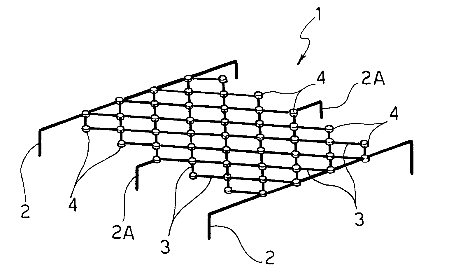
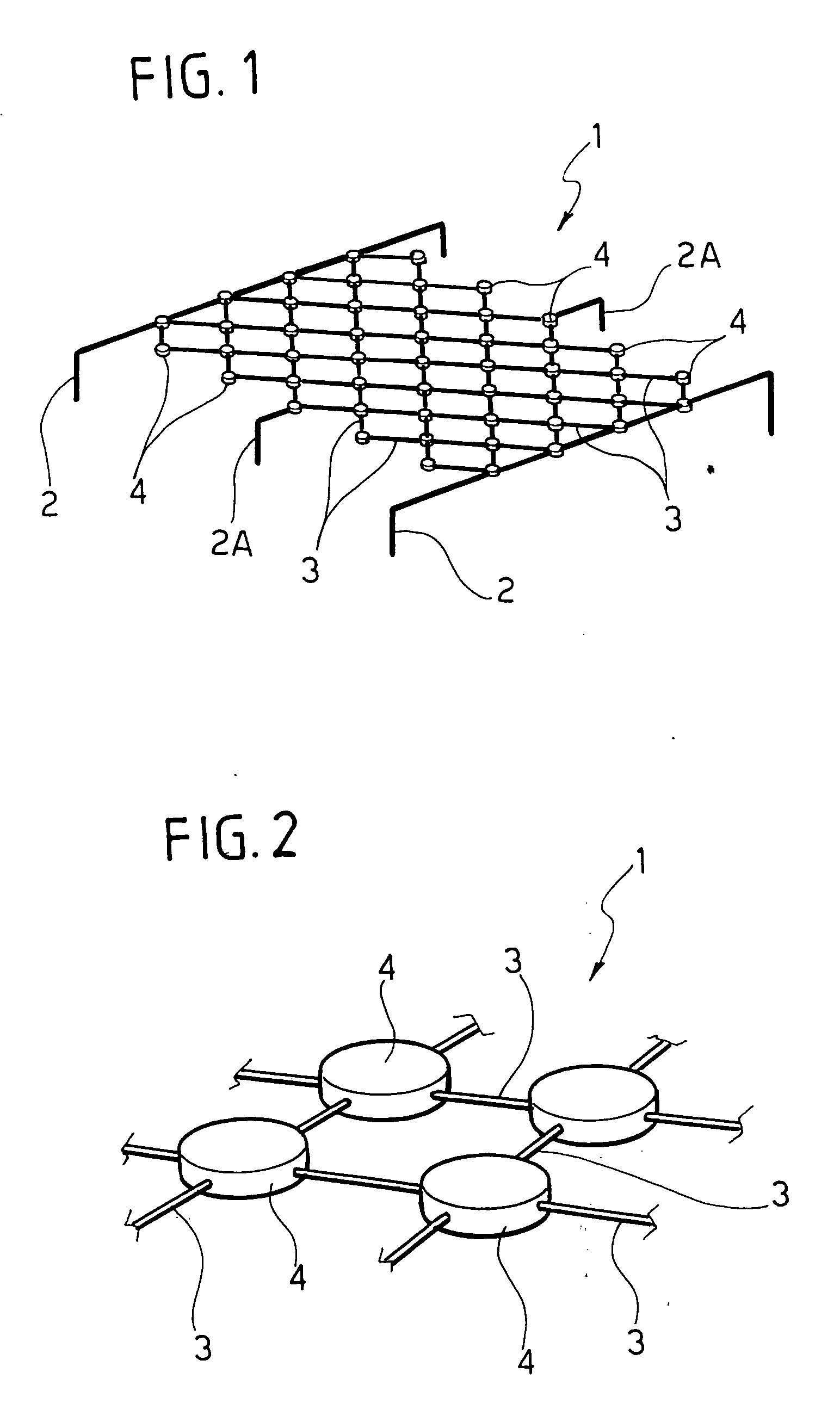
[0030] In FIG. 1, the reference number globally designates a filament matrix produced in accordance with the teaching of the present invention.
[0031] The matrix 1 comprises two lateral power supply conductors 2 made of metallic material and a plurality of micro-filaments 3, where the term “micro-filaments” means individual pieces of filament that emit light when an appropriate electrical current flows through them, reaching a temperature of about 2800° K.
[0032] The various micro-filaments 3 are arranged according to a “net” configuration, and are then mechanically and electrically connected to each other as well as to the conductors 2; the reference number 2A designates hooks for the positioning and support of the matrix 1, also connected to some micro-filaments 3. For this purpose, also with reference to FIG. 2, the reference number 4 designates the connections between some micro-filaments 3.
[0033] The elementary filament of the matrix 1 can be in different forms: individual wir...
PUM
| Property | Measurement | Unit |
|---|---|---|
| electrical conductivity | aaaaa | aaaaa |
| density | aaaaa | aaaaa |
Abstract
Description
Claims
Application Information