Hollow core fiber laser induced incandescence

a hollow core fiber and laser induced incandescence technology, applied in the direction of optical radiation measurement, instruments, spectrometry/spectrophotometry/monochromators, etc., can solve the problems of physical obstruction, need for installation windows,

Inactive Publication Date: 2011-09-22
UNIVERSITY OF ALABAMA
View PDF11 Cites 3 Cited by
  • Summary
  • Abstract
  • Description
  • Claims
  • Application Information

AI Technical Summary

Problems solved by technology

There are several disadvantageous issues associated with open optic systems including, exposure of potentially dangerous laser beams, maintaining alignment of both delivery and signal optics, access to physically obstructed locations (laser beams and light signals only travel in straight lines in open optic systems), and the need for installing windows to provide optical access to the region under test.

Method used


Image

  • Hollow core fiber laser induced incandescence
  • Hollow core fiber laser induced incandescence
  • Hollow core fiber laser induced incandescence

Examples


Embodiment Construction

[0048]The following examples are put forth so as to provide those of ordinary skill in the art with a complete disclosure and description of how the compounds, compositions, articles, devices and / or methods claimed herein are made and evaluated, and are intended to be purely exemplary of the invention and are not intended to limit the scope of what the inventors regard as their invention. Efforts have been made to ensure accuracy with respect to numbers (e.g., amounts, temperature, etc.), but some errors and deviations should be accounted for. Unless indicated otherwise, parts are parts by weight, temperature is in ° C. or is at ambient temperature, and pressure is at or near atmospheric.

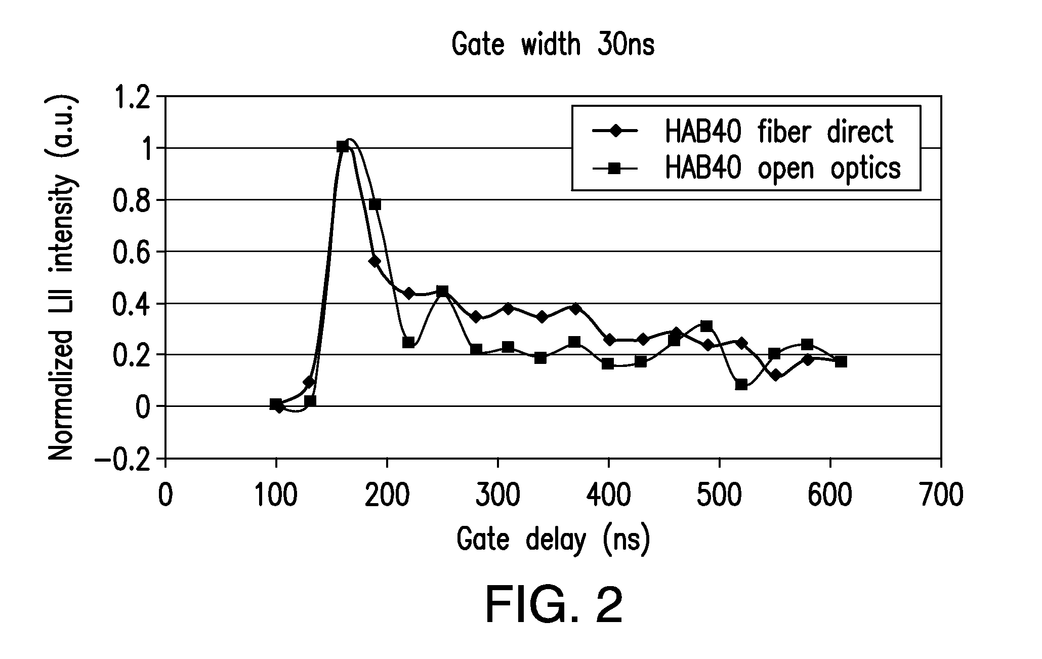
[0049]In a first example, an LII system was utilized to measure particles from a rich ethylene flame. Multiple individual measurements were obtained using a CCD camera at increasingly delayed time relative to the laser pulse. Comparisons were made between LII systems utilizing open optic systems and...


PUM

PropertyMeasurementUnit
poweraaaaaaaaaa
wavelength sensitiveaaaaaaaaaa
visible light wavelength rangeaaaaaaaaaa

Abstract

The present disclosure relates to measurement techniques utilizing laser induced incandescence, and specifically to laser induced incandescence measurement techniques utilizing a hollow core fiber.

Description

CROSS REFERENCE TO RELATED APPLICATIONS[0001]This application claims the benefit of priority to U.S. Provisional Application No. 61 / 314,859, filed Mar. 17, 2010, which application is incorporated by reference herein in its entirety.FIELD[0002]The present disclosure relates to measurement techniques utilizing laser induced incandescence, and specifically to laser induced incandescence measurement techniques utilizing a hollow core fiber.TECHNICAL BACKGROUND[0003]Laser-induced incandescence (LII) has been used as a diagnostic technique for the determination of soot-particle volume fraction and size. Traditional LII techniques heat up particles with short laser pulses. The temperature of the analyte particles is increased to a point to produce significant incandescence of the particle. This induced thermal radiation can then be detected to establish the presence of the particles and further analyzed to determine certain particle characteristics. The incandescence from the particles is ...

Claims


Application Information

Patent Timeline
Patent Type & Authority Applications(United States)
IPC IPC(8): G01N21/59G01J5/00G01N21/47
CPCG01N15/06G01N2015/0693G01N21/71G01N21/47
Inventor PUZINAUSKAS, PAULIUS V.DUMITRESCU, COSMIN E.
Owner UNIVERSITY OF ALABAMA
Why Eureka
Try Eureka