Adjustable-aim light pipe fixture

a technology for fixing fixtures and light pipes, which is applied in the direction of lighting support devices, lighting and heating apparatus, instruments, etc., can solve the problems of not facilitating fixture adjustment, affecting the adjustment of the fixture, so as to minimize damage or deformation, avoid damage or deformation, and facilitate adjustmen

Inactive Publication Date: 2006-01-05
ENERGY FOCUS INC
View PDF5 Cites 12 Cited by
  • Summary
  • Abstract
  • Description
  • Claims
  • Application Information

AI Technical Summary

Benefits of technology

[0014] The foregoing light pipe fixture can be easily adjusted, while reliably holding a desired aim of the light fixture. In fact, in one embodiment, a user can adjust the aim of the fixture from below the fixture with a common screwdriver. The foregoing embodiment minimizes damage or deformation to the surface of the eyeball, while ...

Problems solved by technology

However, these alternatives make access to the eyeball for adjustment of the light after the fixture has been mounted in place nearly impossible or very difficult without access to behind a mounting frame or some sort of unique adjustment tool.
Necessitating the use of a unique adjustment tool not only complicates the fixture by requiring a separate, non-readily available tool to adjust the fixture after final adjustments, but it also does not facilitate adjustment of the fixture at-will unless the adjustment tool is available.
A problem that exists with currently available eyeball fixtures is the inability to capture the eyeball between a retention means that is strong enough to firmly lock the eyeball in place (1) without rotating the eyeball within the socket during capture, (2) without damaging the finish on the eyeball, or (3) without deforming the eyeball.
Another problem that exists with currently available fixtures is the inability to easily adjust the fixture, in a reliable or accurate manner, at some future time after firmly positioning the fixture after final adjustments.
This difficulty is exacerbated with fiber optic fixtures, since the forces within the fiber tend to move the fixture out of adjustment over time as the fiber curves away from the fixture or the fixture moves out of adjustment during capture of the eyeball within a retention means.
However, inclusion of a strain relief tends to increase the total fixture height and precludes the use of such fixtures in low-clearance areas.
Another problem that may attribute to the inability to easily adjust a fixture, such as an eyeball fixture, after installation is the amount of pressure that a retaining means places on the eyeball in order to retain the eyeball firmly in place with respect to a retention means.
However, as stated previously, this solution complicates use of the fixture.
In addition, this solution does not cr...

Method used


Image

  • Adjustable-aim light pipe fixture
  • Adjustable-aim light pipe fixture
  • Adjustable-aim light pipe fixture

Examples


Embodiment Construction

[0041] This description is divided into three parts: (1) adjustable-aim light pipe fixture, (2) designs for the foregoing, adjustable-aim lighting fixture, and (3) bayonet and receiver assemblies used in the adjustable-aim light pipe fixture.

1. Adjustable-Aim Light Pipe Fixture

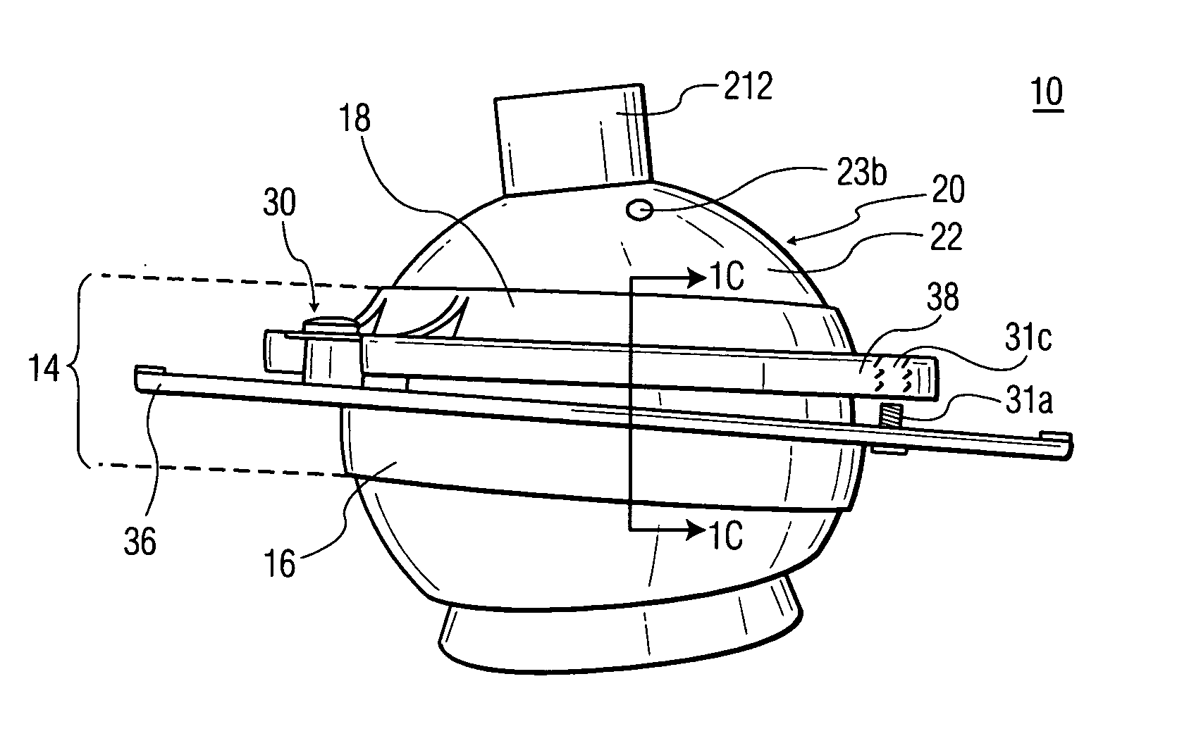
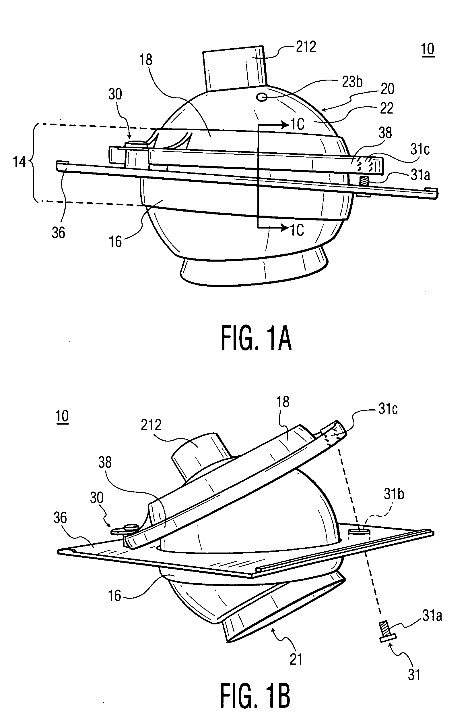
[0042]FIGS. 1A and 1B show an overview of a preferred embodiment of an inventive arrangement 10 for an adjustable lighting fixture. Arrangement 10, which is typically used with a mounting arrangement 212 for a fiber optic light pipe (omitted in this figure), preferably includes a socket 14 comprising a first retainer ring 16 and a second retainer ring 18, a spherical eyeball 20, and a clamping structure 30, 31.

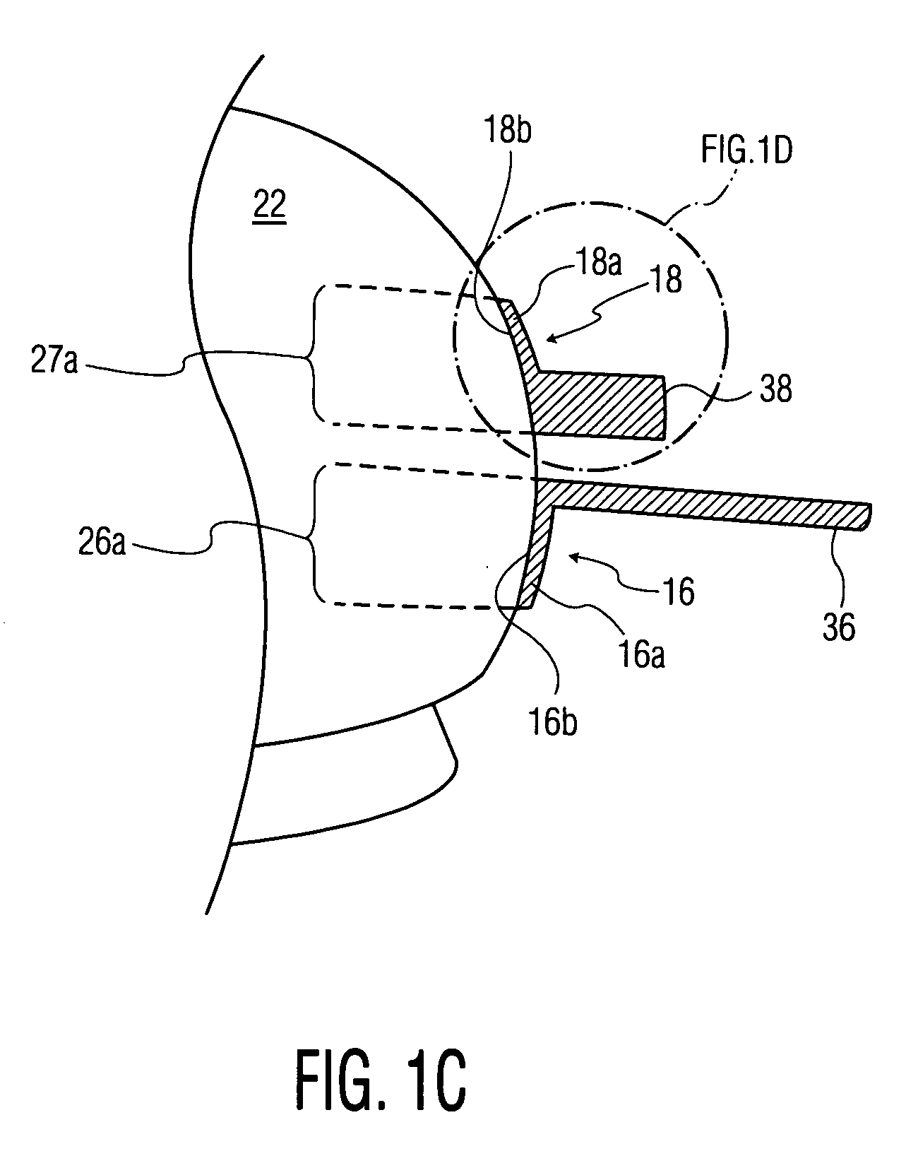
[0043] Eyeball 20 is generally spherical in shape. A spherical surface 22 of eyeball 20 allows rotatable adjustment of the position of eyeball 20, as received in relation to first retainer ring 16 of socket 14.

[0044] First retainer ring 16 is preferably affixed to a socket mounting plate 36 for mount...


PUM


Abstract

An adjustable-aim light pipe fixture, comprising a generally spherical eyeball for receiving an end of a light pipe is disclosed. The eyeball has a longitudinal axis coincident with a longitudinal axis of that portion of the light pipe that is received in the eyeball. A socket holds the eyeball. The socket comprises a first retainer ring and a second retainer ring. Each retainer ring has an interior surface with contact points to an outer surface of the eyeball. The first and second retainer rings are oriented with respect to each other so as to hold the eyeball in a fixed position when the first and second rings are pressed towards each other. Clamping structure clamps the first and second rings against each other in such manner as to hold the eyeball in fixed relation to the first retainer ring.

Description

[0001] This application claims priority from U.S. Provisional Application No. 60 / 584,359, filed on Jun. 30, 2004. CROSS REFERENCE TO RELATED APPLICATION [0002] The present application is related to U.S. application Ser. No. 10 / 793,049, filed Mar. 4, 2004, entitled Light Pipe Fixture, by the same inventors as the present inventors.FIELD OF THE INVENTION [0003] The present invention relates to fixtures for a light pipe with various features to allow for the fixture to be precisely aimed, for instance. BACKGROUND OF THE INVENTION [0004] A variety of arrangements have been proposed in the prior art for adjusting the orientation of a fiber optic lighting fixture after the fixture has been mounted in place. The arrangements typically involve either a gimbaled sphere that can be locked in place onto either a mounting frame or another gimbal, or a spherical eyeball that is captured between a flange and a retention means, which requires an adjusting tool to adjust the eyeball after the eyeba...

Claims


Application Information

Patent Timeline
IPC IPC(8): F21V8/00
CPCF21S8/02G02B6/0008F21V21/30F21V14/02
Inventor BUELOW, ROGER F. IIDAVENPORT, JOHN M.FRANKIEWICZ, GREGORY P.BINA, DAVE
Owner ENERGY FOCUS INC
Why Eureka
Try Eureka