
Offset satellite communication cell arrays with orthogonal polarizations

Inactive Publication Date: 2006-01-05
SPACECODE +1
View PDF3 Cites 10 Cited by
  • Summary
  • Abstract
  • Description
  • Claims
  • Application Information

AI Technical Summary

Benefits of technology

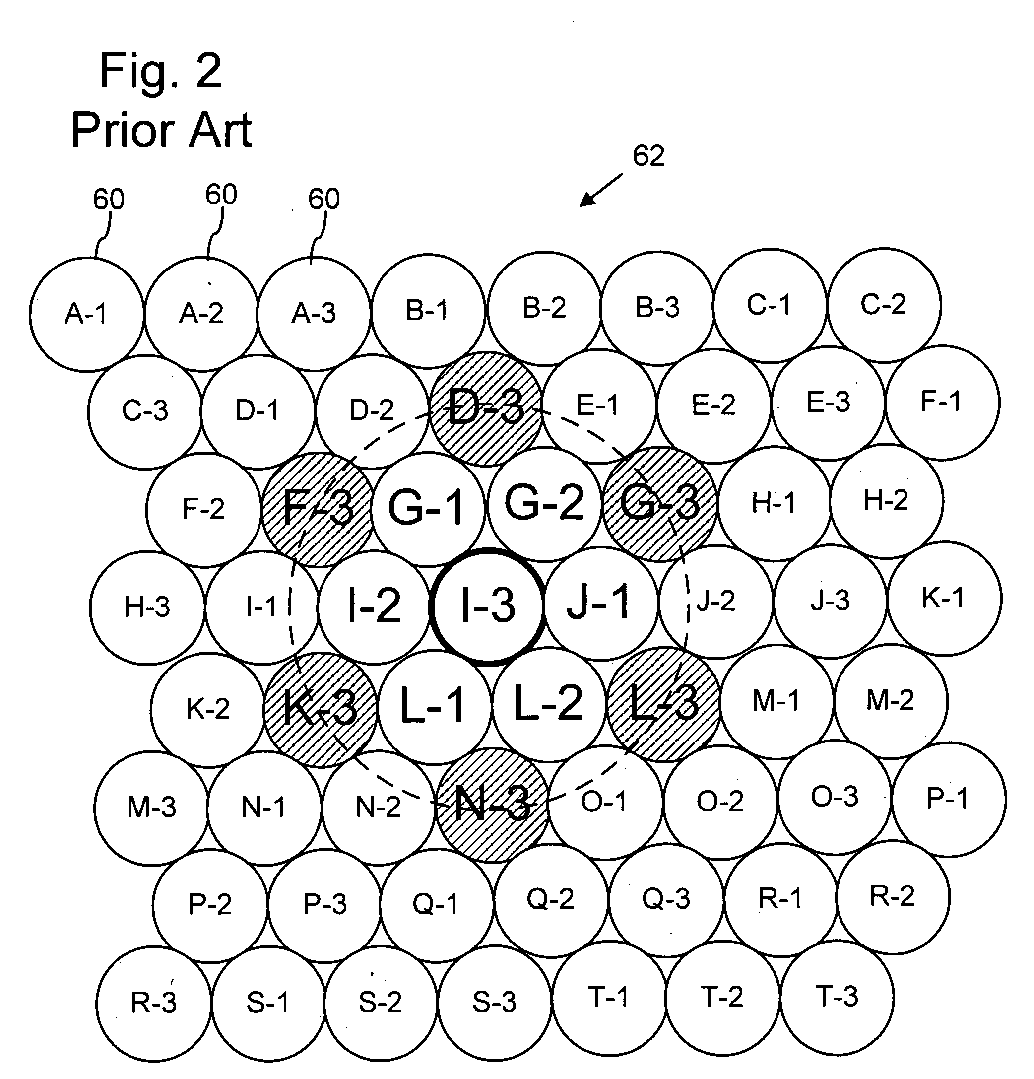
[0004] The conventional communication satellite directs narrow zone communication signals to recipient stations in multiple cells over a satellite telecommunication region. The cells correspond to different geographic areas within the region and may form a dense-packed or “honeycombed,” optionally overlapping, arrangement that minimizes or eliminates the portions of region not covered by a cell. Next adjacent cells typically receive distinct communication signals or sub-bands. However, potentially interfering cells are typically within the telecommunication region. As a result, cells can have interference-induced signal-to-noise ratios (S / Nint) at a maximum of about 20 dB at the center of a cell with decreases to about 12 dB at the peripheries of the cells. A consequence of such a range of signal-to-noise ratios within a cell is that signal integrity and reliability is decreased at the cell peripheries.
[0007] The satellite of the present invention provides reduced interference between cells that receive potentially interfering signals by interposing cells that receive non-interfering signals. As a result, communication signals are delivered with increased uniformity in the signal-to-noise ratios, which can noticeably improve signal reliability or allow the finite communication signal power to be allocated to more areas.

Problems solved by technology

However, potentially interfering cells are typically within the telecommunication region.

Method used


Image

  • Offset satellite communication cell arrays with orthogonal polarizations
  • Offset satellite communication cell arrays with orthogonal polarizations
  • Offset satellite communication cell arrays with orthogonal polarizations

Examples


Embodiment Construction

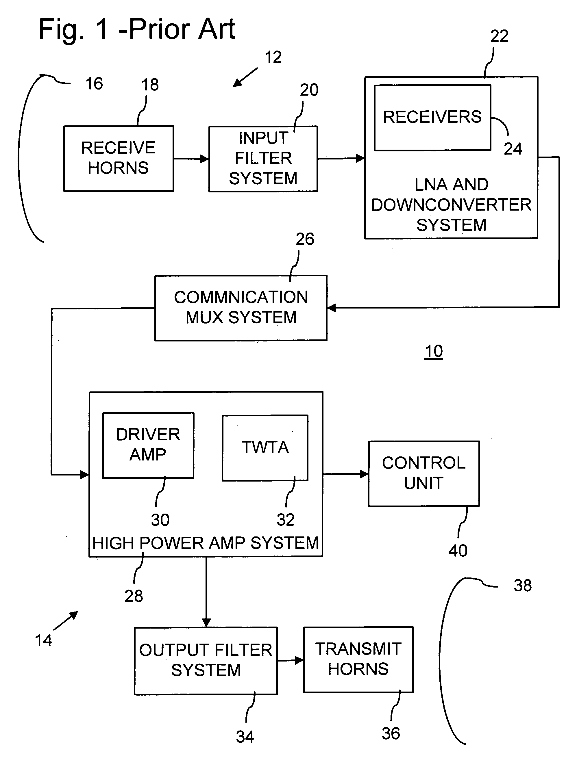
[0017]FIG. 1 is a block diagram of a prior art implementation of a communication satellite 10 for geosynchronous orbit, as described in U.S. Pat. No. 6,275,479 and assigned to Spacecode LLC, the assignee of the present invention. Communication satellite 10 has a communication signal receiving system 12 and a communication signal transmitting system 14. Receiving system 12 includes a satellite receiving reflector 16 that receives multiple communication uplink signals from one or more terrestrial transmitting stations and concentrates the signals at corresponding ones of multiple receiving horns 18. Receiving horns 18 pass the communication uplink signals through an input filter system 20 to a satellite low noise amplifier (LNA) and downconverter system 22 having multiple individual receivers 24. Each of the uplink communication signals may include multiple separate signals.

[0018] Low noise amplifier (LNA) and downconverter system 22 would typically include more individual receivers ...


PUM


Abstract

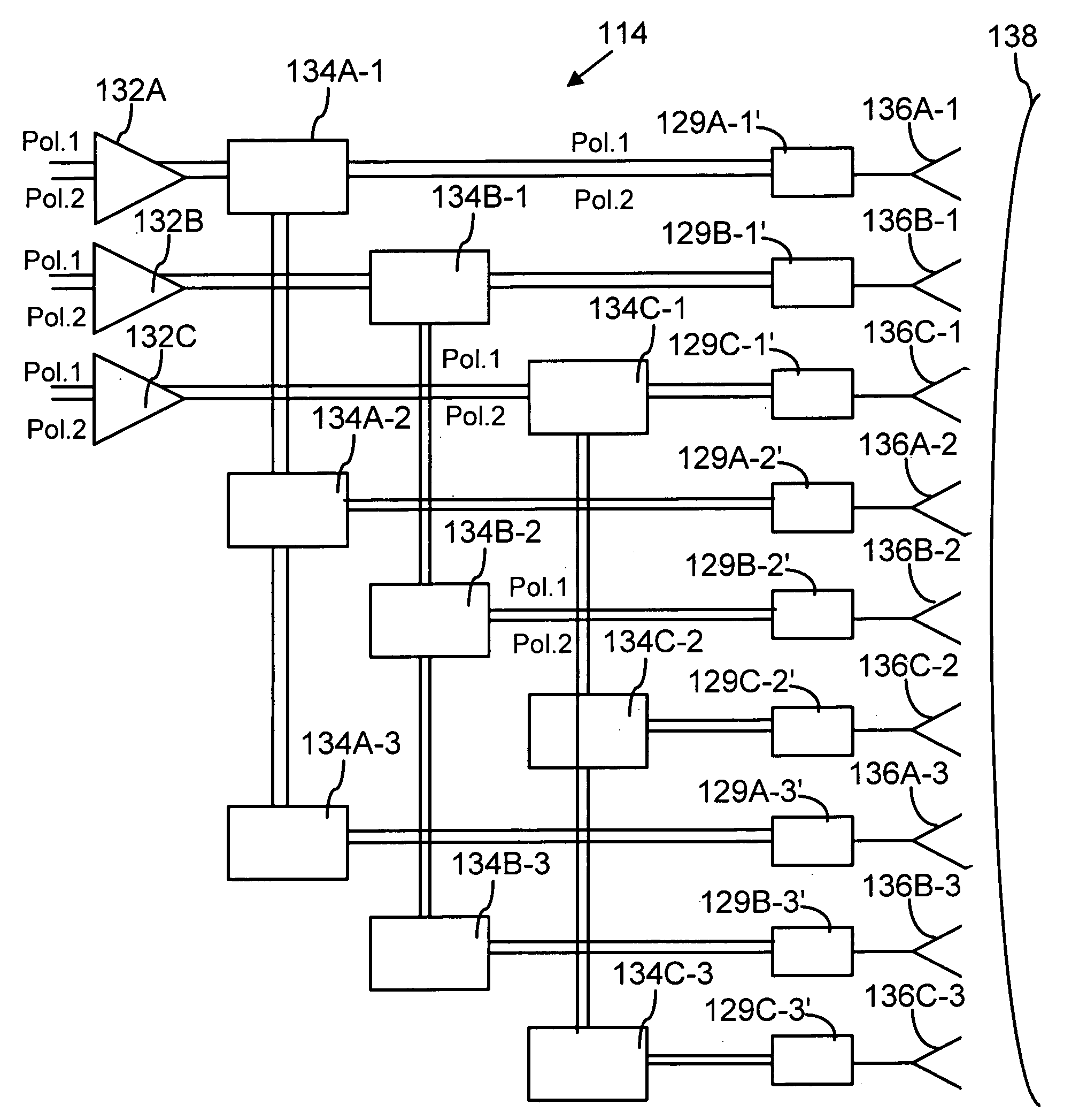
A communication satellite has multiple communication signal amplifiers coupled to multiple transmit horns that transmit communication signals to multiple corresponding geographic cells. The satellite includes a first set of communication signal amplifiers and transmit horns that cooperate to deliver multiple distinct communication signals of a first polarization to a first array of multiple adjacent geographic cells having interstices or intersections between them. The satellite also includes a second set of communication signal amplifiers and transmit horns that cooperate to deliver multiple distinct communication signals of a second polarization to a second array of multiple adjacent geographic cells having interstices or intersections between them. The first and second polarizations are orthogonal to each other, such as horizontal and vertical polarizations or right- and left-circular polarizations. In addition, the adjacent geographic cells of the first array are generally centered at the interstices between and overlap the cells of the second array, and the cells of the second array are generally centered at the interstices between and overlap the cells of the first array.

Description

FIELD OF THE INVENTION [0001] The present invention relates to satellite communication systems and, in particular, to a communication satellite that provides offset arrays of geographical cells with communication signals of orthogonal polarizations. BACKGROUND AND SUMMARY OF THE INVENTION [0002] A conventional communication satellite in geosynchronous orbit has a communication signal receiving system and a communication signal transmitting system. The receiving system includes a satellite receiving reflector that receives multiple communication uplink signals from one or more terrestrial transmitting stations and concentrates the signals at corresponding ones of multiple receiving horns, which pass the communication uplink signals through an input filter system to a satellite low noise amplifier (LNA) and downconverter system. [0003] A communication multiplexer system receives the low noise amplified and frequency converted uplink signals and channelizes and routes the signals to th...

Claims


Application Information

Patent Timeline
IPC IPC(8): H04B7/216H04B7/204
CPCH04B7/2041
Inventor THOMPSON, MARK D.BUCCA, STEVE
Owner SPACECODE
Learn More