Long wavelength vertical cavity surface emitting lasers

a laser and vertical cavity technology, applied in semiconductor lasers, laser details, optical resonator shape and construction, etc., can solve the problems of inability to scale devices to smaller sizes, inability to form significant optical guiding, and large guide siz

Inactive Publication Date: 2006-01-05
II VI DELAWARE INC
View PDF13 Cites 35 Cited by
  • Summary
  • Abstract
  • Description
  • Claims
  • Application Information

AI Technical Summary

Benefits of technology

[0012] An advantage of the present invention provides VCSELs having independently definable current and optical guides that provide unique forms of drive current and transverse mode confinement, respectively.
[0013] Additional features and advantages of the invention will be set forth in the description which follows, and in part will be apparent from the description, or may be learned by practice of the invention. These and other advantages of the invention will be realized and attained by the structure particularly pointed out in the written description and claims hereof as well as the appended drawings.
[0014] To achieve these and other advantages and in accordance with the purpose of the present invention, as embodied and broadly described, a long wavelength vertical cavity surface emitting laser (VCSEL) may, for example, include a first distributed Bragg reflector (DBR); a second DBR, wherein t

Problems solved by technology

However, due to ion straggle and other difficulties associated with deep ion implantation, this current guide must be relatively large (e.g., >10 μm).
Both of these factors inhibit scaling the devices to smaller sizes.
In addition, the ion-implanted VCSEL does not form any significant optical guiding; i.e., it does not provide refractive index guiding of

Method used


Image

  • Long wavelength vertical cavity surface emitting lasers
  • Long wavelength vertical cavity surface emitting lasers
  • Long wavelength vertical cavity surface emitting lasers

Examples


first embodiment

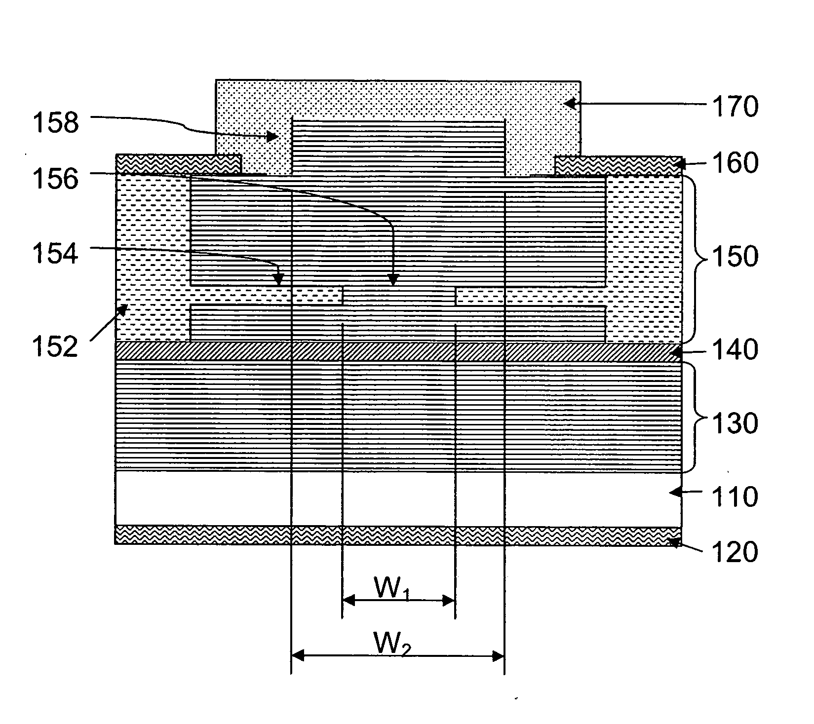
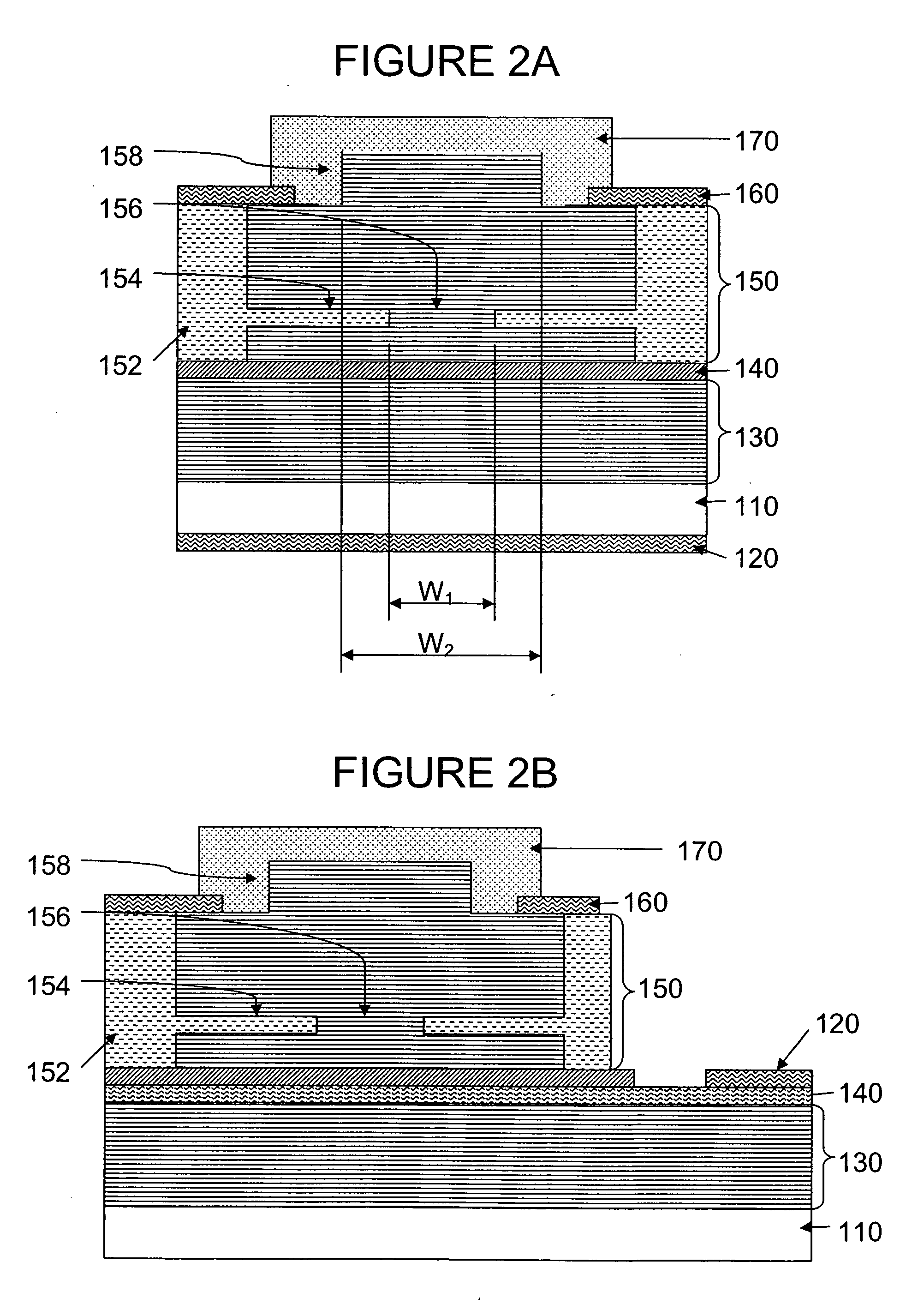
[0037] Referring to FIG. 2A, a VCSEL 200 according to the present invention may, for example, include an n-type InP substrate 110, a bottom metallic layer 120 formed on a bottom surface of the substrate 110, a semiconductive n-type bottom distributed Bragg reflector (DBR) 130 formed on an upper surface of the substrate 110, an active region 140 formed on the bottom DBR 130, a semiconductive p-type top DBR 150 formed on the active region 140, a top metallic layer 160 formed on the semiconductor top DBR 150, and a dielectric structure 170 formed on the semiconductor top DBR 150 and, optionally, over the metallic layer 160. In one aspect of the present invention, the interface between the dielectric structure 170 and the semiconductor top DBR 150 may be substantially free of voids. In another aspect of the present invention, the dielectric structure 170 may be provided as a multi-layered dielectric DBR.

[0038] In one aspect of the present invention, the top metallic layer 160 may serve ...

third embodiment

[0054] Further the dielectric structure 170 may be provided as dielectric passivation layer including a single dielectric material. In one aspect of the present invention, the dielectric passivation layer 170 may be formed by substantially any suitable method.

[0055] Referring to FIG. 3B, a VCSEL 500 according to a fourth embodiment of the present invention may, for example, be similar to the VCSEL of the second embodiment previously described with respect to FIG. 2B; however, the semiconductor top DBR 150 may include the at least one intracavity optical aperture 153 discussed above with respect to FIG. 3A.

[0056] Referring to FIG. 4A, a VCSEL 600 according to a fifth embodiment of the present invention may, for example, be similar to the VCSEL of the first embodiment previously described with respect to FIG. 2A; however, adjacent VCSEL devices may be substantially electrically isolated via a trench design 155. In one aspect of the present invention, the trench design 155 may, for e...

seventh embodiment

[0058] Referring to FIG. 5A, a VCSEL 800 according to the present invention may, for example, be similar to the VCSEL previously described with respect to FIG. 3A; however, the semiconductor top DBR 150 may include the trench design 155 discussed above with respect to FIG. 4A.


PUM


Abstract

A vertical cavity surface emitting laser (VCSEL) includes independently definable current and optical confinement structures that provide unique forms of drive current and transverse mode confinement, respectively. The optical guide may be formed from an upper distributed Bragg reflector (DBR), as an etched mesa structure and/or as an intracavity optical guide. The current guide may include an ion-implanted region within the upper DBR. A dielectric structure is formed over the upper DBR and surrounds the optical guide.

Description

CROSS-REFERENCE TO RELATED APPLICATIONS [0001] This application claims benefit to U.S. Provisional Application Ser. No. 60 / 583,980, filed on Jun. 30, 2004, which is incorporated herein.BACKGROUND OF THE INVENTION [0002] 1. Field of the Invention [0003] The present invention relates generally to vertical cavity surface emitting lasers (VCSELs). More particularly, the present invention relates to VCSELs which provide independently definable current confinement and optical mode confinement. [0004] 2. Field of the Invention [0005] As compared with conventional edge-emitting semiconductor lasers, vertical cavity surface emitting lasers (VCSELs) hold the promise of a number of desirable characteristics. For example, shorter cavity resonator VCSELs provide excellent mode selectivity and, therefore, narrower linewidths. Use of multi-layered distributed Bragg reflectors (DBRs) to form a cavity resonator perpendicular to the layers obviates the need for cleaving operations common to edge emit...

Claims


Application Information

Patent Timeline
IPC IPC(8): H01S5/00
CPCH01S5/024H01S5/0422H01S5/18308H01S5/18327H01S2301/166H01S5/18369H01S5/18377H01S5/2063H01S5/18341
Inventor WANG, TZU-YUKIM, JIN K.
Owner II VI DELAWARE INC
Why Eureka
Try Eureka