Fuel cell and electronic device equipped with the same

a fuel cell and electronic device technology, applied in the field of fuel cells, can solve the problems of lower than expected output and power output decline, and achieve the effects of high output, high efficiency and high efficiency

Inactive Publication Date: 2006-01-05
HITACHI LTD
View PDF14 Cites 15 Cited by
  • Summary
  • Abstract
  • Description
  • Claims
  • Application Information

AI Technical Summary

Benefits of technology

[0008] Basically, the liquid fuel 4 has an optimum methanol concentration for maximizing power generating efficiency of a fuel cell. However, in a fuel cell with membrane electrode assemblies arranged two-dimensionally, uneven methanol concentration on a planar area will cause problems resulting from a lower than expected output even when fuel cell capacity is increased to produce high output.
[0009] The present invention is developed to solve these problems. It is an object of the present invention to provide a fuel cell which can supply a fuel of uniform concentration to its membrane electrode assemblies to generate power at a high efficiency.

Problems solved by technology

However, the aqueous solution of such a high methanol concentration, when used as a liquid fuel, will cause the crossover phenomenon, in which the membrane electrode assembly 2 passes more methanol molecules than water molecules to deteriorate activity on the air side, decreasing power output.
However, in a fuel cell with membrane electrode assemblies arranged two-dimensionally, uneven methanol concentration on a planar area will cause problems resulting from a lower than expected output even when fuel cell capacity is increased to produce high output.

Method used


Image

  • Fuel cell and electronic device equipped with the same
  • Fuel cell and electronic device equipped with the same
  • Fuel cell and electronic device equipped with the same

Examples


first embodiment

[0057] The first embodiment of the present invention is described by referring to from FIG. 1(A-D) to FIG. 4.

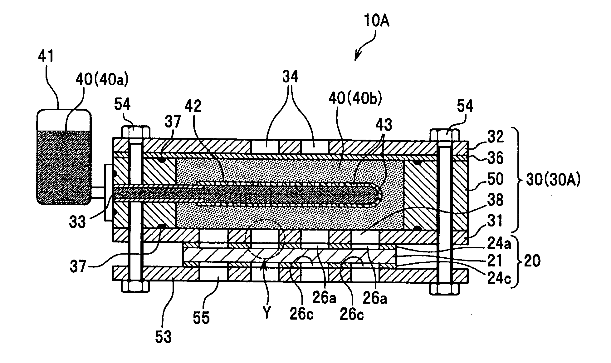
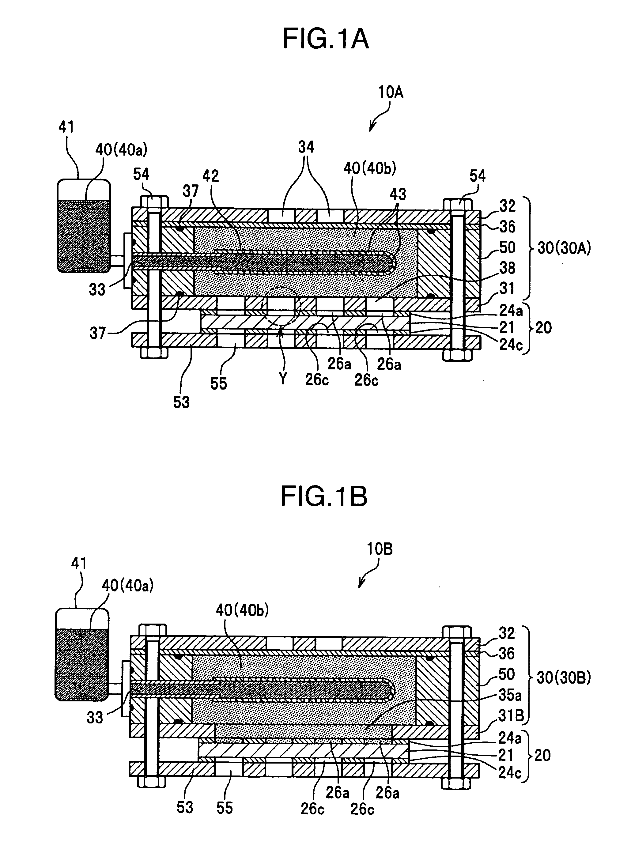
[0058] Referring to FIG. 1A, the fuel cell 10A is mainly composed of the membrane electrode assembly module 20 which consumes the liquid fuel 40 to generate power, fuel chamber 30A from which the liquid fuel 40 is supplied to the membrane electrode assembly module 20, fuel supply device 41 which holds the liquid fuel 40 outside of the fuel chamber 30A, fuel supply gear 42 which supplies the liquid fuel 40 from the fuel supply device 41 to the vicinity of each membrane electrode assembly module 20, and holding plate 53 which presses the membrane electrode assembly module 20 to, and fixes it on, the fuel chamber 30A. The fuel supply device 41 and fuel supply gear 42 are in communication with each other via the fuel injection hole 33, to send the liquid fuel 40 from the fuel supply device 41 to the fuel supply gear 42 under pressure.

[0059] As illustrated in FIG. 2, the membran...

second embodiment

[0096] Next, the other fuel cell types of the second embodiment are described by referring to FIGS. 5 and 6.

[0097] As shown in FIG. 5, the fuel cell 10E of this embodiment has a plurality of the membrane electrode assembly modules 20 which are electrically connected to each other in series or parallel and arranged two-dimensionally on the principal plane plate 31E for the fuel chamber 30E.

[0098] A plurality of the membrane electrode assembly modules 20 shown in FIG. 6 are connected to each other in series, where the negative terminal 25a of the membrane electrode assembly module 20 is connected to the positive terminal 25c of the adjacent module 20 to establish the series circuit as a whole. The line of the modules 27 is provided with interconnections at both ends to transmit power output to the outside.

[0099] When a plurality of the membrane electrode assembly modules 20 are connected in parallel, the collecting plates for anode 24a of the adjacent modules 20B are connected to e...


PUM

PropertyMeasurementUnit
porosityaaaaaaaaaa
diameteraaaaaaaaaa
diameteraaaaaaaaaa

Abstract

It is an object of the present invention to provide a fuel cell which can supply a liquid fuel, without changing its composition, to every corner of the membrane electrode assemblies arranged two- dimensionally over a wide area, to generate power at a high efficiency.
The fuel cell 10A comprises the membrane electrode assembly modules 20 which consume the liquid fuel 40 to generate power, and the fuel chamber 30 which holds the liquid fuel 40 inside and has the principal plane on which the membrane electrode assembly modules 20 are arranged, wherein the fuel chamber 30 is provided with the fuel injection hole 33 inside, through which the liquid fuel 40 is supplied under pressure from the outside, and the fuel supply gear 42 inside, which is located to come close to the membrane electrode assembly modules 20, the fuel supply gear 42 being provided, on the surface, with the fine pores 43 through which the liquid fuel 40 can pass.

Description

BACKGROUND OF THE INVENTION [0001] The present invention relates to a fuel cell, in particular a fuel cell having one or more membrane electrode assembly modules, and electronic device equipped with the fuel cell. [0002] Recently, direct methanol fuel cells (DMFCs), which directly use methanol as a liquid fuel to generate power, have been attracting attention as portable power sources capable of driving codeless devices, e.g., laptops, continuously for extended periods. Therefore, they are strongly demanded to be compacter for satisfying these purposes. As part of the efforts to satisfy these demands, various attempts have been made to develop fuel cells of reduced size or increased power output, e.g., arranging membrane electrode assemblies (MEAs) as power-generating elements two-dimensionally or electrically connecting them to each other in series. [0003]FIG. 8 is a sectional view of conventional fuel cell. [0004] The conventional fuel cell 1 comprises a plurality of membrane elec...

Claims


Application Information

Patent Timeline
Patent Type & Authority Applications(United States)
IPC IPC(8): H01M8/00
CPCH01M8/04186H01M8/04201Y02E60/50H01M8/1011Y02E60/523H01M8/04208
Inventor KOHNO, RYUJINAGATA, TATSUYAKITANO, MAKOTO
Owner HITACHI LTD
Why Eureka
Try Eureka