Gap-filling for isolation

a technology of gap-filling and isolation, applied in the direction of basic electric elements, semiconductor/solid-state device manufacturing, electric devices, etc., can solve problems such as unwanted gaps, and achieve the effect of increasing the oxidation rate of the semiconductor layer

Inactive Publication Date: 2006-01-05
INFINEON TECH AG
View PDF12 Cites 21 Cited by
  • Summary
  • Abstract
  • Description
  • Claims
  • Application Information

AI Technical Summary

Benefits of technology

[0009] In another aspect, the invention avoids discontinuities such as voids in the filling material.
[0018] According to another preferred embodiment of the invention, the step of annealing is carried out in a steam environment as a steam environment enhances the oxidation rate of the semiconductor layer.

Problems solved by technology

As stated above, many problems with respect to the filling of gaps are caused by the shrinkage of the gap fill oxide during further process steps, which results in unwanted voids.

Method used


Image

  • Gap-filling for isolation
  • Gap-filling for isolation
  • Gap-filling for isolation

Examples


Embodiment Construction

[0020] The making and using of the presently preferred embodiments are discussed in detail below. It should be appreciated, however, that the present invention provides many applicable inventive concepts that can be embodied in a wide variety of specific contexts. The specific embodiments discussed are merely illustrative of specific ways to make and use the invention, and do not limit the scope of the invention.

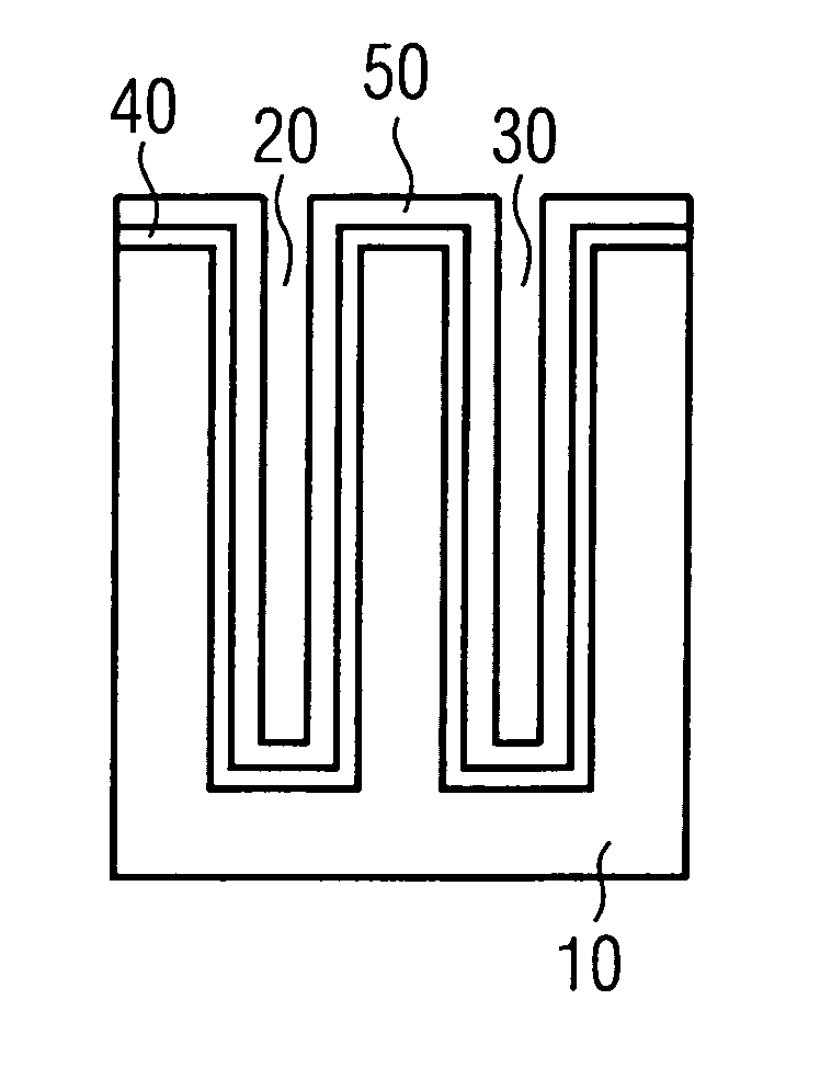
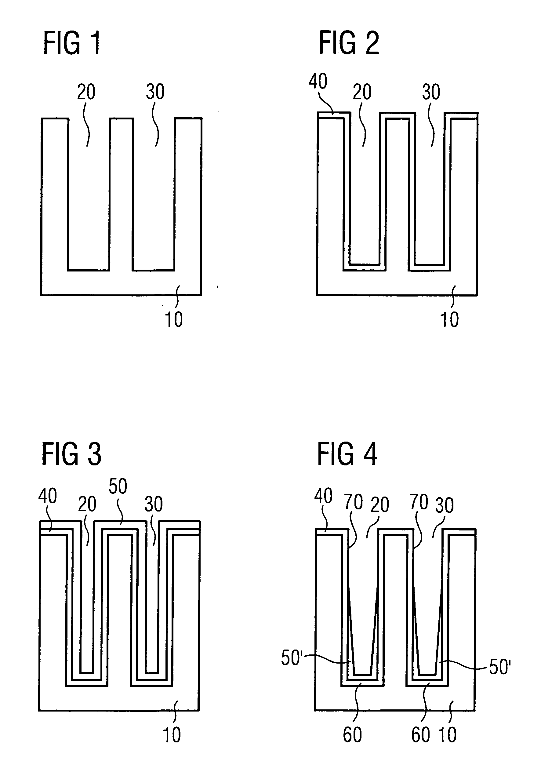
[0021]FIG. 1 shows a silicon substrate 10 having two trenches 20 and 30. The trenches are etched in a usual way, e.g., using an oxide or nitride hard mask. An SiN-liner (i.e., layer) 40 is deposited on the substrate 10 and on the trenches 20 and 30 (FIG. 2). The SiN-liner 40 protects the underlying silicon structure and makes sure that the silicon structure cannot be oxidized in further process steps.

[0022] On top of the SiN-liner 40, a conformal oxide liner 50, preferably a TEOS-based oxide liner, is deposited. The resulting structure is shown in FIG. 3. The process param...


PUM


Abstract

A method of filling high ratio trenches on a substrate is described. First, an oxidizable layer is deposited on the substrate. Thereafter, a trench fill oxide is deposited on the substrate and on the oxidizable layer. Afterwards, the resulting structure is annealed using an oxygen containing gas such that the oxidizable layer is oxidized.

Description

TECHNICAL FIELD [0001] This invention relates generally to a method of filling high ratio gaps such as trenches on substrates used in the fabrication of semiconductor devices, wafers and the like. BACKGROUND [0002] In order to physically and electrically separate electronic elements of a semiconductor device from one another, shallow insulating trenches are located therebetween. As semiconductor technology advances, semiconductor devices become more dense. Therefore, the width of the insulating trenches decreases, resulting in increasing “aspect ratios” (trench height / trench width) of the trenches. In consequence, trench filling with insulating materials such as oxides becomes more and more difficult. In order to avoid discontinuities or voids in the trench filling material, many approaches can be found in the literature. [0003] The international patent application WO 00 / 60659, which is related to U.S. Pat. No. 6,387,764, discloses a trench isolation method, wherein a trench fill ox...

Claims


Application Information

Patent Timeline
Patent Type & Authority Applications(United States)
IPC IPC(8): H01L21/76
CPCH01L21/76235H01L21/76224H01L21/76
Inventor KLIPP, ANDREASSTAVREV, MOMTCHILHAUPT, MORITZ
Owner INFINEON TECH AG
Why Eureka
Try Eureka