Methods and apparatus for visualization of quantitative data on a model

a quantitative data and model technology, applied in the field of diagnostic ultrasound methods and systems, can solve the problems of inability of ultrasonic methods and systems to present quantitative time data with surface model rendering techniques

a quantitative data and model technology, applied in the field of diagnostic ultrasound methods and systems, can solve the problems of inability of ultrasonic methods and systems to present quantitative time data with surface model rendering techniques

US20060004291A1Inactive Publication Date: 2006-01-05GENERAL ELECTRIC CO

Image

  • Methods and apparatus for visualization of quantitative data on a model
  • Methods and apparatus for visualization of quantitative data on a model
  • Methods and apparatus for visualization of quantitative data on a model

Examples


Embodiment Construction

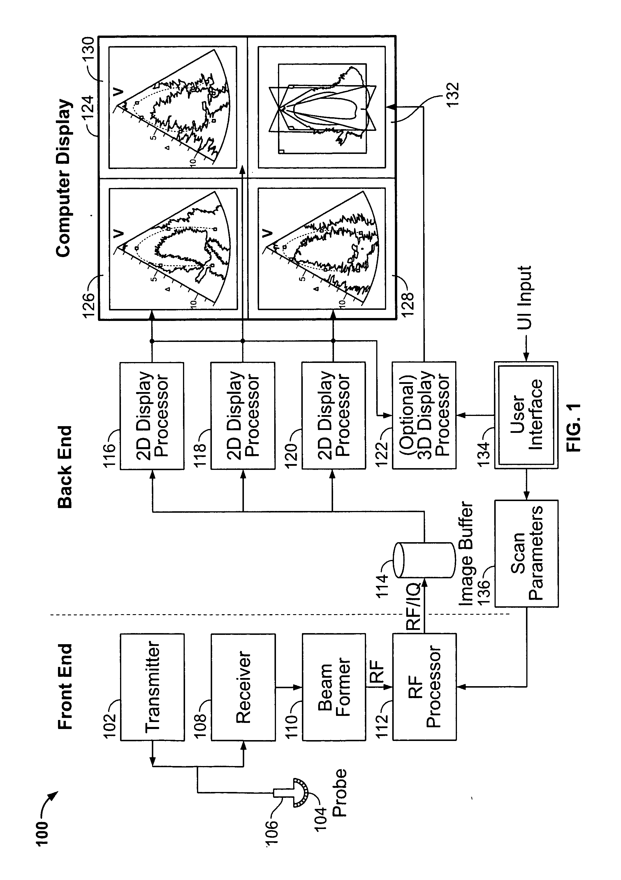
[0017]FIG. 1 is a block diagram of an ultrasound system 100 formed in accordance with an embodiment of the present invention. The ultrasound system 100 is configurable to acquire information corresponding to a plurality of two-dimensional (2D) representations or images of a region of interest (ROI) in a subject or patient. One such ROI may be the human heart or the myocardium of a human heart. The ultrasound system 100 is configurable to acquire 2D image planes in two or more different planes of orientation. The ultrasound system 100 includes a transmitter 102 that, under the guidance of a beamformer 110, drives a plurality of transducer elements 104 within an array transducer 106 to emit pulsed ultrasound signals into a body. The elements 104 within the array transducer 106 are excited by an excitation signal received from the transmitter 102 based on control information received from the beamformer 110. When excited, the transducer elements 104 produce ultrasonic waveforms that ar...


PUM


Abstract

An ultrasound method for visualization of quantitative data on a surface model is provided. The ultrasound method acquires ultrasound information from an object. The information acquired defines ultrasound images along at least first and second scan planes through the object and is stored in a buffer memory. The method then constructs a surface model of the object based on the ultrasound information. Timing information associated with local areas on the object is determined. The surface model and timing information are displayed with the timing information being positioned proximate regions of the surface model corresponding to local areas on the object.

Description

CROSS REFERENCE TO RELATED APPLICATIONS [0001] This application claims priority to and the benefit of the filing date of U.S. Provisional Application No. 60 / 581,675 filed on Jun. 22, 2004 and which is hereby incorporated by reference in its entirety.BACKGROUND OF THE INVENTION [0002] The present invention relates to diagnostic ultrasound methods and systems. In particular, the present invention relates to methods and systems for visualizing ultrasound data sets on a model. [0003] Numerous ultrasound methods and systems exist for use in medical diagnostics. Various features have been proposed to facilitate patient examination and diagnosis based on ultrasound images of the patient. For example, certain systems offer various techniques for obtaining volume rendered data. Systems have been developed to acquire information corresponding to a plurality of two-dimensional representations or image planes of an object for three-dimensional reconstruction and surface modeling. [0004] Heretof...

Claims


Application Information

Patent Timeline
05 Jan 2006
Publication
US20060004291A1
IPC
A61B8/12; A61B8/00
CPC
A61B8/08; A61B8/0883; A61B8/145; A61B8/485; A61B8/467; A61B8/483; A61B8/463; A61B8/469
Inventors
HEIMDAL, ANDREAS; RABBEN, STEIN INGE