Method and system for flow measurement and validation of a mass flow controller

a mass flow controller and flow measurement technology, applied in water supply installation, valve operating means/release devices, instruments, etc., can solve the problems of reducing tool availability, adding cost to users, and measuring small flow is extraordinarily time-consuming, so as to reduce sensitivity to pressure transients, accurate determination of total volume, and minimizing false flow conditions

Active Publication Date: 2006-01-12
BROOKS INSTRUMENT +1
View PDF31 Cites 40 Cited by
  • Summary
  • Abstract
  • Description
  • Claims
  • Application Information

AI Technical Summary

Benefits of technology

[0013] Systems and methods for flow verification and validation of mass flow controllers are disclosed. These systems and methods are capable of measuring the dynamic performance of a mass flow controller and may perform flow verification and measurement in one step. Two volumes may be used in conjunction to accurately determine a total volume during a measurement sequence, minimize false flow conditions and reduce sensitivity to pressure transients. A mass flow controller may be coupled to a measurement system. The mass flow controller may be commanded to a specified flow and the system may begin flow measurement. Gas is accumulated in a volume between the mass flow controller and the measurement system and the pressure measured within this volume. Gas may then flow into a known volume and the pressure measured. The various measurements taken during the two intervals may then be used to calculate the volume between the mass flow controller and the measurement system and the flow rate. The flow rate, in turn, may be used to determine the accuracy of the mass flow controller relative to a setpoint.

Problems solved by technology

Unfortunately, the volume of typical process chamber 130, which may be on the order of 20 to 60 liters makes measurements of small flow extraordinarily time consuming.
This lengthy validation cycle decreases the tool availability and adds cost to the user.
In addition to the slowness of the measurement, the accuracy of the measurement is typically no better than + / −5% of the reading.
The primary contributing errors are: errors in temperature, errors in chamber volume, and unaccounted for gases (adsorption or desorption).
However, these methods do not allow the measuring of transient (non steady-state) performance of mass flow controller 120, and the many steps required to determine the volume upstream of mass flow controller 120 make this technique difficult to integrate into existing systems and may exacerbate already long time requirements for validation.

Method used


Image

  • Method and system for flow measurement and validation of a mass flow controller
  • Method and system for flow measurement and validation of a mass flow controller
  • Method and system for flow measurement and validation of a mass flow controller

Examples


Embodiment Construction

[0029] The invention and the various features and advantageous details thereof are explained more fully with reference to the nonlimiting embodiments that are illustrated in the accompanying drawings and detailed in the following description. Descriptions of well known starting materials, processing techniques, components and equipment are omitted so as not to unnecessarily obscure the invention in detail. It should be understood, however, that the detailed description and the specific examples, while indicating preferred embodiments of the invention, are given by way of illustration only and not by way of limitation. After reading the specification, various substitutions, modifications, additions and rearrangements which do not depart from the scope of the appended claims will become apparent to those skilled in the art from this disclosure.

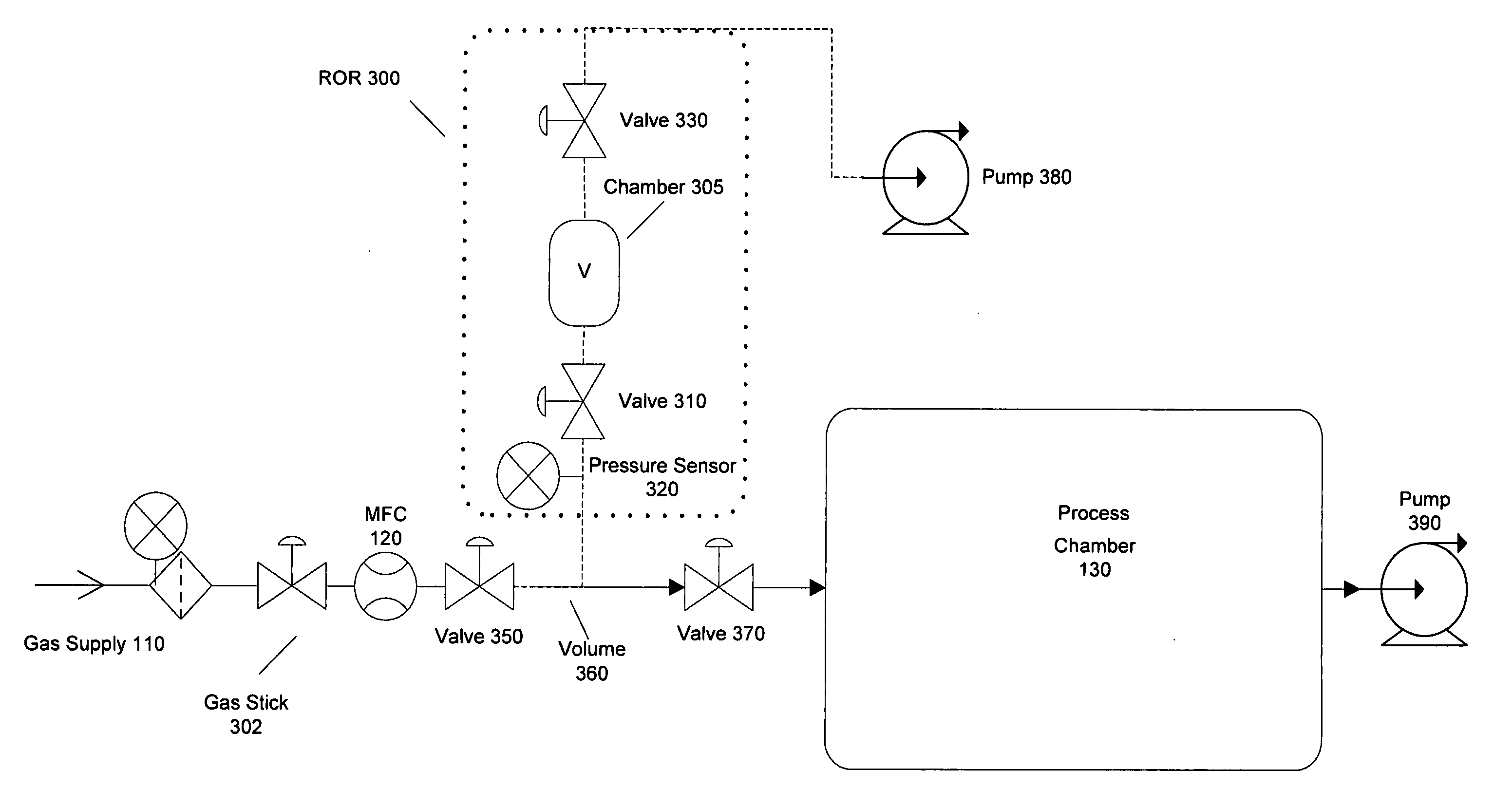
[0030] Attention is now directed to systems and methods for flow verification and validating flow controllers which are capable of measuring t...


PUM


Abstract

Systems and methods for flow verification and validation of mass flow controllers are disclosed. A mass flow controller may be commanded to a specified flow and flow measurement commenced. Gas is accumulated in a first volume and while measurements are taken within this volume. Gas may then flow into a second volume while measurements are taken. The various measurements taken during the two intervals may then be used to calculate the flow rate. The flow rate, in turn, may be used to determine the accuracy of the mass flow controller relative to a setpoint. Additionally, these systems and methods may utilize only one volume to perform flow verification by flowing gas into this volume, taking measurements, and calculating the flow rate based only upon this set of measurements.

Description

RELATED APPLICATIONS AND PATENTS [0001] This application is related to U.S. Pat. No. 6,343,617, entitled “System and Method of Operation of a Digital Mass Flow Controller,” by Tinsley et al., issued on Feb. 5, 2002; U.S. Pat. No. 6,640,822, entitled “System and Method of Operation of a Digital Mass Flow Controller,” by Tinsley et al., issued on Nov. 4, 2003; U.S. Pat. No. 6,681,787, entitled “System and Method of Operation of a Digital Mass Flow Controller,” by Tinsley et al., issued on Jan. 27, 2004; U.S. Pat. No. 6,389,364, entitled “System and Method for a Digital Mass Flow Controller,” by Vyers, issued on May 14, 2002; U.S. Pat. No. 6,714,878, entitled “System and Method for a Digital Mass Flow Controller,” by Vyers, issued on Mar. 30, 2004; U.S. Pat. No. 6,445,980, entitled “System and Method for a Variable Gain Proportional-Integral (PI) Controller,” by Vyers, issued on Sep. 3, 2002; U.S. Pat. No. 6,449,571, entitled “System and Method for Sensor Response Linearization,” by Ta...

Claims


Application Information

Patent Timeline
Patent Type & Authority Applications(United States)
IPC IPC(8): G05D7/06
CPCG01F25/0053G01F25/0038Y10T137/7761Y10T137/0379Y10T137/7759Y10T137/0324G01F25/17G01F25/15
Inventor TISON, STUART A.SUKUMARAN, SANDEEPBARKER, JAMES
Owner BROOKS INSTRUMENT
Why Eureka
Try Eureka