Inductively-driven light source for lithography

a lithography and inductive drive technology, applied in the direction of magnetic discharge control, instruments, therapy, etc., can solve the problem that the electrode emits undesirable particle emissions from the light source of the plasma

Active Publication Date: 2006-01-12
HAMAMATSU PHOTONICS KK
View PDF33 Cites 5 Cited by
  • Summary
  • Abstract
  • Description
  • Claims
  • Application Information

AI Technical Summary

Problems solved by technology

As a result, however, the plasma light sources generate undesirable particle emissions from the electrodes.

Method used


Image

  • Inductively-driven light source for lithography
  • Inductively-driven light source for lithography
  • Inductively-driven light source for lithography

Examples


Embodiment Construction

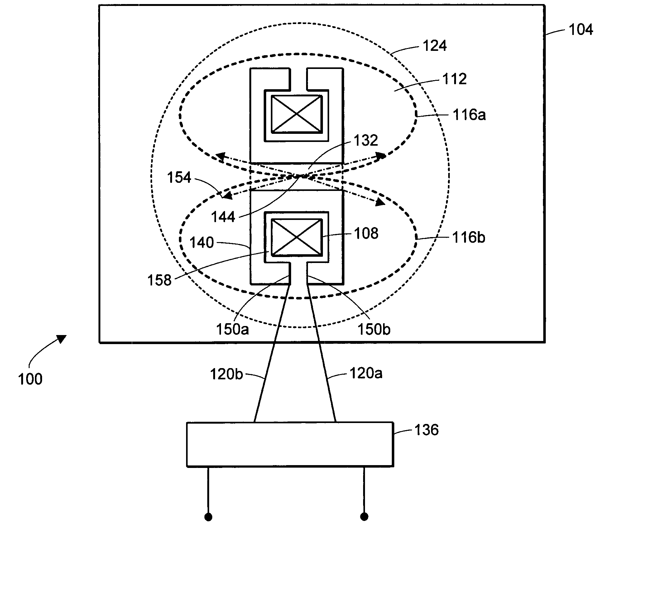
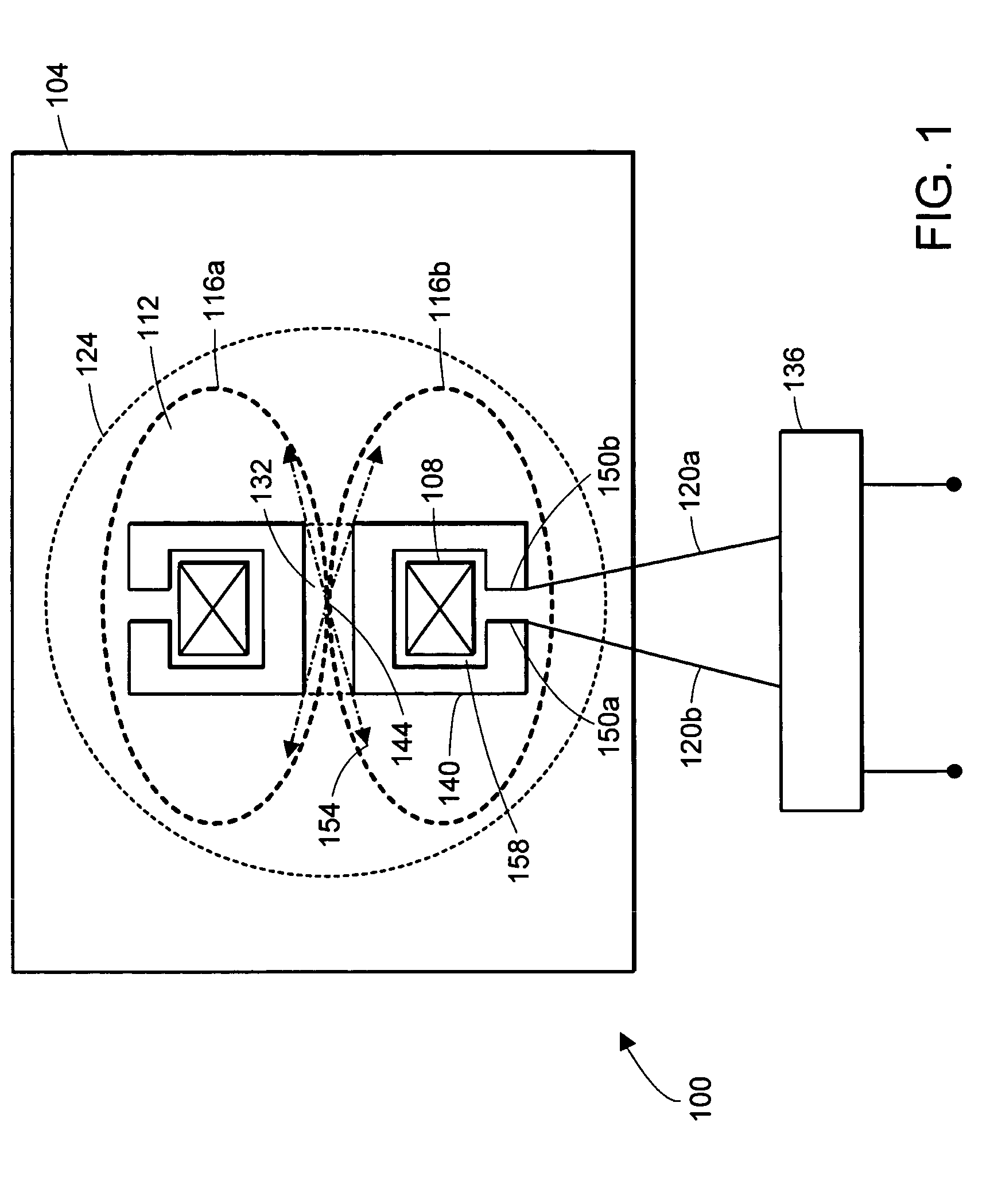
[0047]FIG. 1 is a cross-sectional view of a plasma source 100 for generating a plasma that embodies the invention. The plasma source 100 includes a chamber 104 that defines a plasma discharge region 112. The chamber 104 contains an ionizable medium that is used to generate a plasma (shown as two plasma loops 116a and 116b) in the plasma discharge region 112. The plasma source 100 includes a transformer 124 that induces an electric current into the two plasma loops 116a and 116b (generally 116) formed in the plasma discharge region 112. The transformer 124 includes a magnetic core 108 and a primary winding 140. A gap 158 is located between the winding 140 and the magnetic core 108.

[0048] In this embodiment, the winding 140 is a copper enclosure that at least partially encloses the magnetic core 108 and that provides a conductive path that at least partially encircles the magnetic core 108. The copper enclosure is electrically equivalent to a single turn winding that encircles the ma...


PUM

PropertyMeasurementUnit
duration of timeaaaaaaaaaa
wavelengthsaaaaaaaaaa

Abstract

An apparatus for producing light includes a chamber that has a plasma discharge region and that contains an ionizable medium. The apparatus also includes a magnetic core that surrounds a portion of the plasma discharge region. The apparatus also includes a pulse power system for providing at least one pulse of energy to the magnetic core for delivering power to a plasma formed in the plasma discharge region. The plasma has a localized high intensity zone.

Description

FIELD OF THE INVENTION [0001] The invention relates to methods and apparatus for generating a plasma, and more particularly, to methods and apparatus for providing an inductively-driven plasma light source for a lithography system. BACKGROUND OF THE INVENTION [0002] Plasma discharges can be used in a variety of applications. For example, a plasma discharge can be used to excite gases to produce activated gases containing ions, free radicals, atoms and molecules. Plasma discharges also can be used to produce electromagnetic radiation (e.g., light). The electromagnetic radiation produced as a result of a plasma discharge can itself be used in a variety of applications. For example, electromagnetic radiation produced by a plasma discharge can be a source of illumination in a lithography system used in the fabrication of semiconductor wafers. Electromagnetic radiation produced by a plasma discharge can alternatively be used as the source of illumination in microscopy systems, for exampl...

Claims


Application Information

Patent Timeline
Patent Type & Authority Applications(United States)
IPC IPC(8): G03F7/20
CPCB82Y10/00H05G2/003G03F7/70033
Inventor SMITH, DONALD K.HORNE, STEPHEN F.BESEN, MATTHEW M.BLACKBOROW, PAUL A.
Owner HAMAMATSU PHOTONICS KK
Why Eureka
Try Eureka