Laser machining of electroactive ceramics

a technology of electroactive ceramics and laser machining, which is applied in piezoelectric/electrostrictive/magnetostrictive devices, piezoelectric/electrostriction/magnetostriction machines, electrical equipment, etc., can solve the problems of brittle ceramic materials, difficult and costly arbitrary shape formation, etc., and achieves cost-effectiveness and greater bending flexibility.

Inactive Publication Date: 2006-01-12
MIDE TECH
View PDF32 Cites 24 Cited by
  • Summary
  • Abstract
  • Description
  • Claims
  • Application Information

AI Technical Summary

Benefits of technology

[0007] The present invention achieves these and other objects by providing a method of machining electroactive ceramics for transducer applications. A Laser-Beam Machining (LBM) process is used to remove material selectively enable cuts, grooves and general forms for transduction. For example, a particularly useful form will be for surface strain relief of planar electroceramics. This introduces greater bending flexibility as well as directional or anisotropic coupling behavior in the material. Other example usages include relief patterns similar to those developed in silicon wafers for Micro ElectroMechanical Structures (MEMS). The LBM process includes through-cuts, grooves and other material removal from a ceramic substrate, and is not necessarily limited to planar structures. This process offers a cost-effective alternative for moderate to large-scale production of flexible, anisotropic sensors and actuators.

Problems solved by technology

Ceramic materials are brittle and are difficult and costly to form in arbitrary shapes.

Method used


Image

  • Laser machining of electroactive ceramics
  • Laser machining of electroactive ceramics
  • Laser machining of electroactive ceramics

Examples


examples

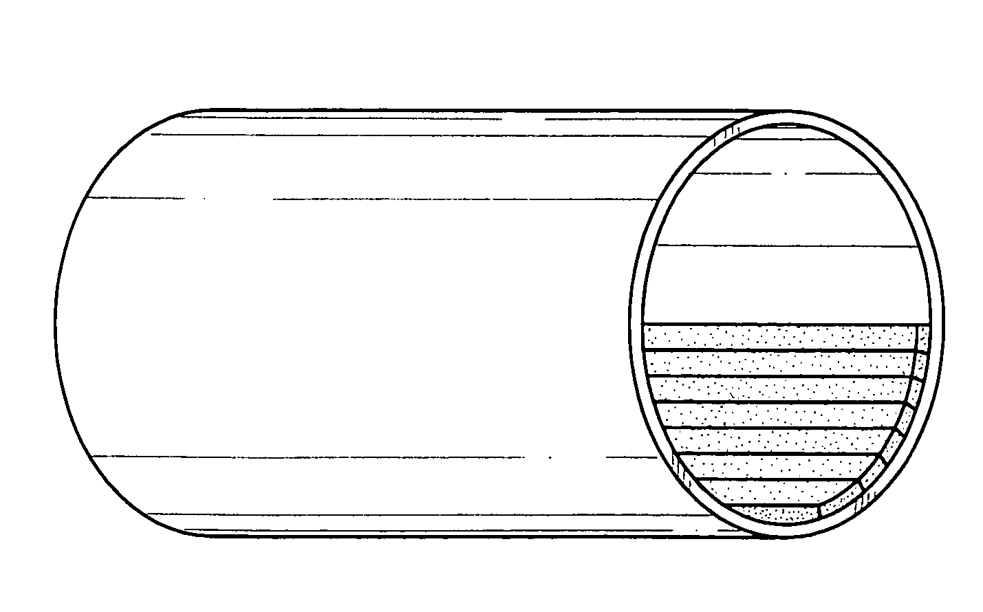
[0031] The LBM technique has been successfully applied to a planar electroceramic wafer. The material was a Lead Zirconate Titanate (PZT-5A) which was initially electroded and poled through the thickness, as received from the manufacturer. A number of parallel grooves were machined into one surface of a 3 inch square wafer which was 0.005 inches thick. The grooves were approximately 0.005 inches wide and were spaced evenly approximately 0.020 inches apart. Beam width was 0.004 inches; slightly more material was removed because of heat transfer in the ceramic. Actuation testing of the test article after machining showed no degradation in induced free strain capability or polarization. In addition, an in-plane anisotropy was measured such that lower strain levels were recorded transverse to the axis of the grooves and greater flexibility was also observed, allowing the wafer to be used, for example, on the surface of a cylinder, as shown in FIGS. 3a-3c. The results indicate that the c...


PUM

PropertyMeasurementUnit
thickaaaaaaaaaa
widthaaaaaaaaaa
radius of curvatureaaaaaaaaaa

Abstract

Laser beam machining is applied to form arbitrarily shaped electroactive ceramics for transducers (e.g., electromechanical sensors and actuators). One particularly preferred embodiment of the invention comprises machining parallel grooves in a ceramic plate to improve flexibility. The grooves provide strain relief in bending by relieving Poisson strains transverse to the direction of bending. This embodiment offers the further benefit that planar anisotropy or directionality is introduced in the transducer. The machining process of the invention further enables the production of more complex geometries than those currently known in the art. Because of the flexibility of the machining process, virtually any desired transducer shape may be produced.

Description

[0001] This application is a Continuation-in-Part and claims the priority of U.S. patent application Ser. No. 10 / 041,919, filed Jan. 8, 2002, which claims priority of U.S. patent application Ser. No. 09 / 264,113, issued as U.S. Pat. No. 6,337,465, the entire contents of which are incorporated by referenced herein.[0002] FIELD OF THE INVENTION [0003] This application relates generally to methods of forming electroactive ceramics by laser machining, and more particularly to methods of producing sensors and actuators having superior mechanical and electroactive properties. BACKGROUND OF THE INVENTION [0004] Ceramic materials are brittle and are difficult and costly to form in arbitrary shapes. In particular, it would be desirable to form electroactive ceramics in more complicated shapes than those currently available. [0005] Some methods of machining ceramics for a variety of reasons have been disclosed. For example, U.S. Pat. Nos. 4,131,484 to Caruso et al., 4,642,505 to Arvanitis, and...

Claims


Application Information

Patent Timeline
Patent Type & Authority Applications(United States)
IPC IPC(8): H01L41/08H01L41/09H01L41/24
CPCH01L41/0926H01L41/43H01L41/335H10N30/204H10N30/085H10N30/097
Inventor MASTERS, BRETT P.RODGERS, JOHN P.VAN SCHOOR, MARTHINUS C.
Owner MIDE TECH
Why Eureka
Try Eureka