Liquid crystal display device and method of driving liquid crystal display device

a liquid crystal display and display device technology, applied in the field of liquid crystal display devices and driving liquid crystal display devices, can solve the problems of slow response speed, inferior image quality to that of cathode ray tubes, and lingering effects

Inactive Publication Date: 2006-01-12
TOSHIBA MATSUSHITA DISPLAY TECH
View PDF4 Cites 16 Cited by
  • Summary
  • Abstract
  • Description
  • Claims
  • Application Information

AI Technical Summary

Benefits of technology

[0070] The present invention can provide a liquid crystal display device free of streaks which are more blackish than the original display color displayed on the display surface of the display panel even when the temperature is low or when each pixel is displayed in the same color such as a halftone color or white color and a method of driving the liquid crystal display device.

Problems solved by technology

However, a TN (Twisted Nematic) aligned liquid crystal panel which is currently used in a wide range has a narrow view angle, a slow response speed and its image quality is inferior to that of a cathode ray tube, for example, when a moving image is displayed its image appears to linger.
However, the double-speed conversion needs to drive each pixel twice as fast as when no counter-transfer prevention drive is performed, and therefore it is difficult to drive the liquid crystal display device.
When the temperature is low, the capacitance of the liquid crystal increases, and therefore insufficient writing to the source line occurs.
This problem that streaks which are more blackish than the original display color appear when the same halftone color is displayed on each pixel is not limited to a 1.25-fold speed conversion whereby the voltage corresponding to the black color is applied to four pixels simultaneously to prevent counter-transfer and then voltages corresponding to the respective display colors are sequentially applied to the four pixels.
The same problem also occurs with a counter-transfer prevention drive whereby voltages corresponding to the black color are applied to n pixels simultaneously to prevent counter-transfer and then voltages corresponding to the respective display colors are sequentially applied to the n pixels.
Furthermore, the same problem also occurs when each pixel is displayed not only with halftone colors but also with white color.
That is, when a counter-transfer prevention drive is performed through a liquid crystal display device using the OCB mode and the temperature is low, if each pixel is displayed in the same color such as a halftone color or white color, there is a problem that streaks which are more blackish than the original display color are displayed on the display surface of the display panel.

Method used


Image

  • Liquid crystal display device and method of driving liquid crystal display device
  • Liquid crystal display device and method of driving liquid crystal display device
  • Liquid crystal display device and method of driving liquid crystal display device

Examples


first embodiment

[0111] First, a first embodiment will be explained.

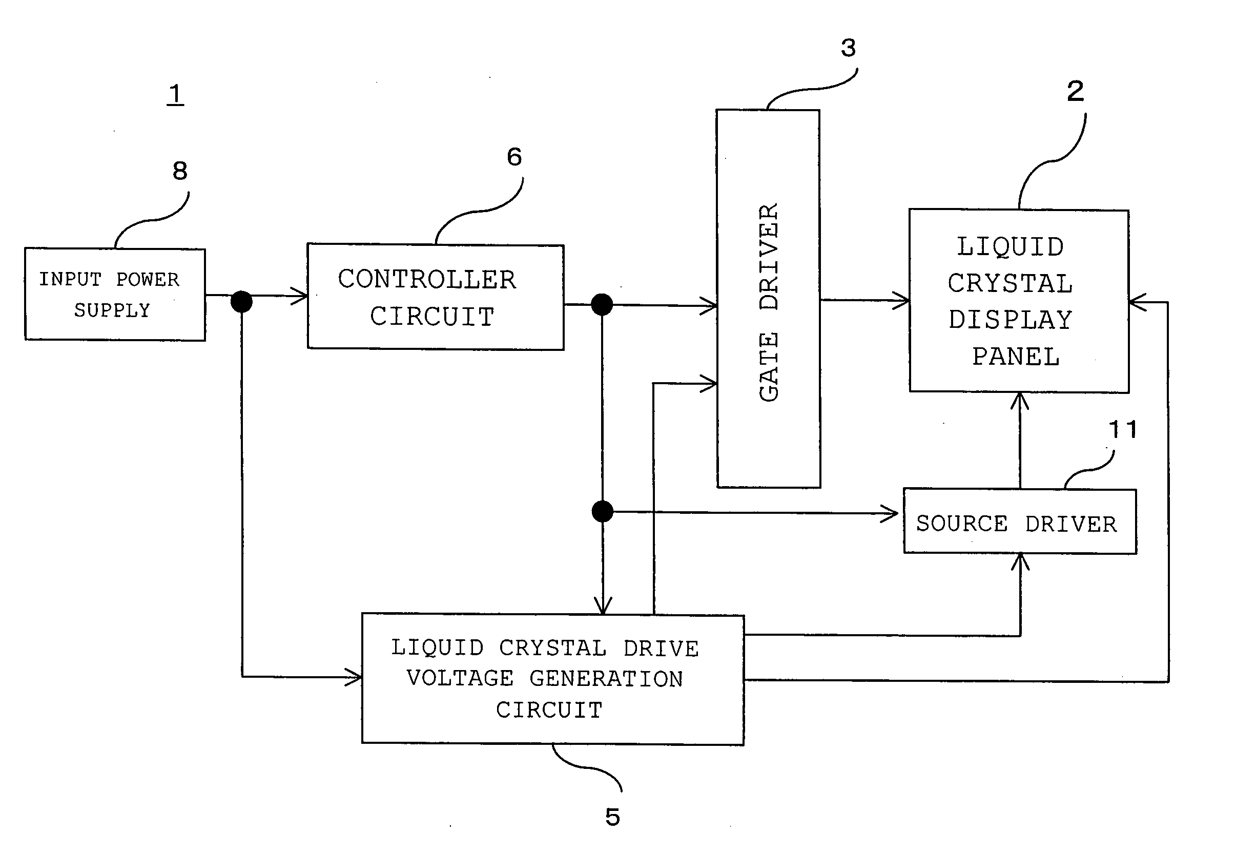
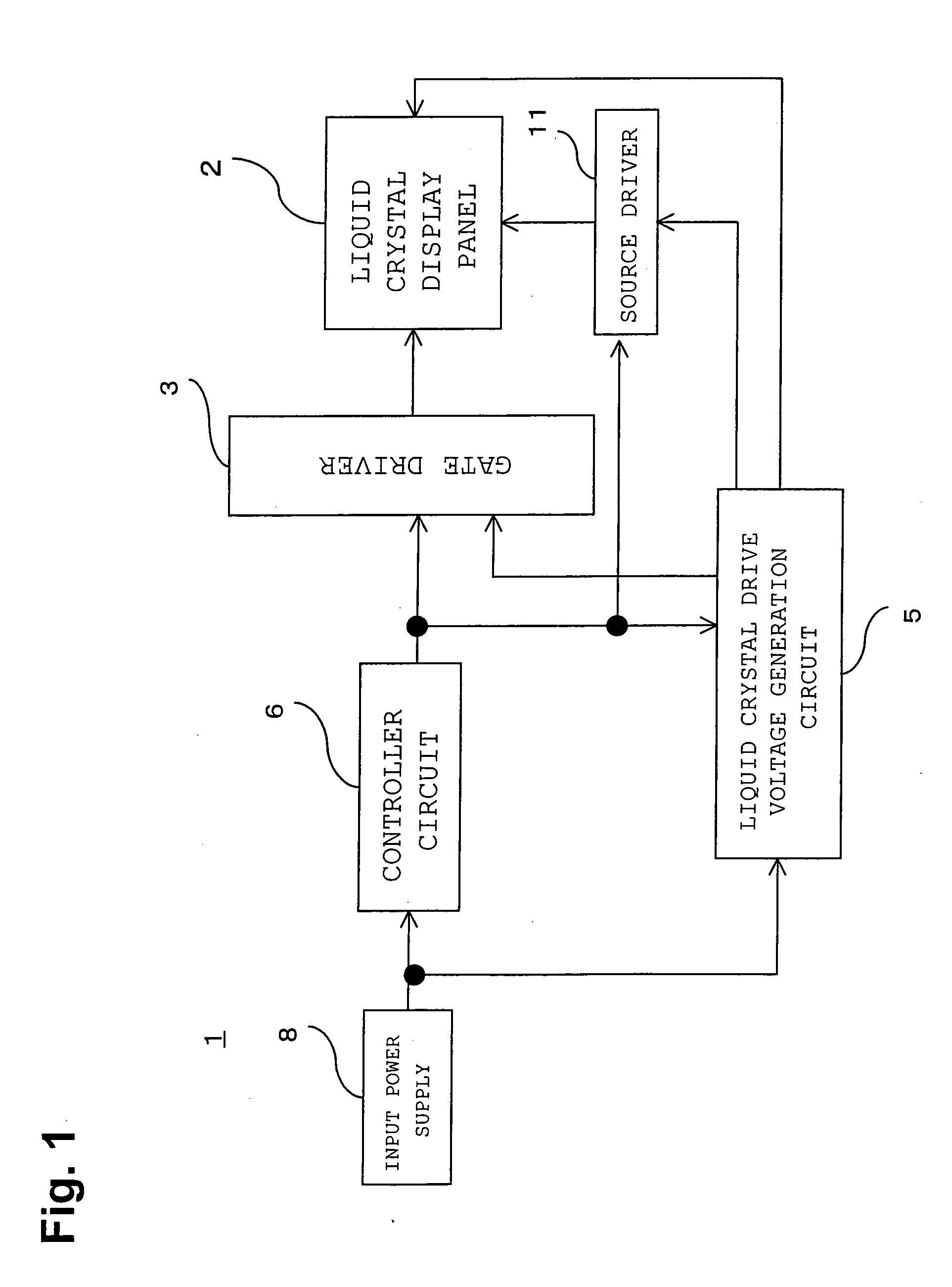
[0112]FIG. 1 shows a block diagram of a liquid crystal play device using an OCB mode of a first embodiment.

[0113] A liquid crystal display device 1 is a liquid crystal play device using OCB mode liquid crystal.

[0114] The liquid crystal display device 1 is constructed of a liquid crystal display panel 2, a gate driver 3, a source driver 11, a liquid crystal drive voltage generation circuit 5, a controller circuit 6 and an input power supply 8.

[0115] The liquid crystal display panel 2 is a display panel having source signal lines and gate signal lines arranged in matrix form and pixels provided at intersections between the source signal lines and gate signal lines and using OCB mode liquid crystal.

[0116] The gate driver 3 is a circuit that supplies a selection scanning signal for carrying out linear sequential scanning of each gate signal line of the liquid crystal display panel 2.

[0117] The source driver 11 is a circuit that su...

second embodiment

[0143] Next, a second embodiment will be explained.

[0144] The configuration of a liquid crystal display device using an OCB mode according to a second embodiment is shown in FIG. 1 in the same way as the first embodiment.

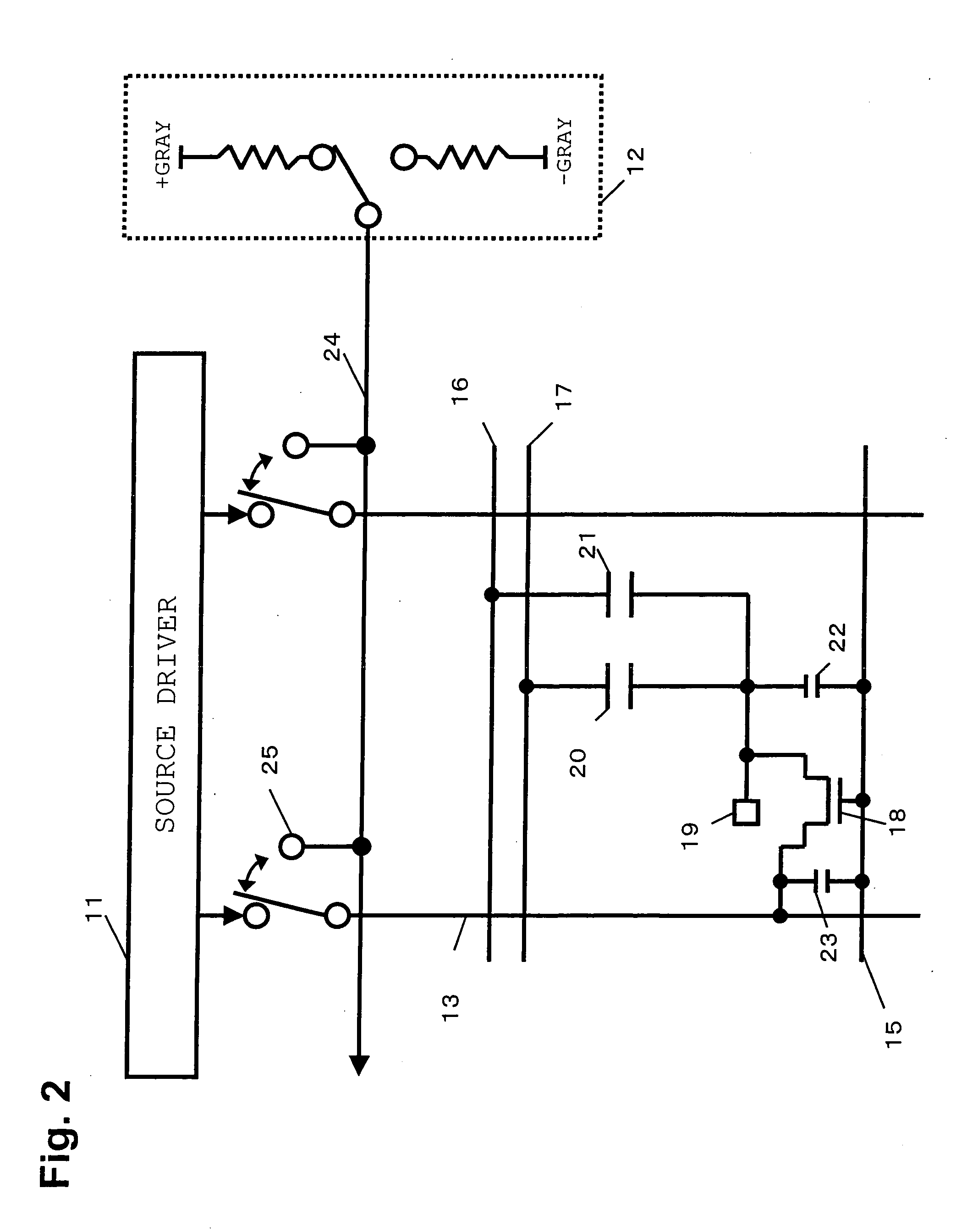
[0145] The difference between the liquid crystal display device using the OCB mode according to the second embodiment and the liquid crystal display device using the OCB mode according to the first embodiment is that the device in the second embodiment is provided with a black insertion voltage generation circuit 14 shown in FIG. 4(b) instead of the black insertion voltage generation circuit 12 in FIG. 2.

[0146] The black insertion voltage generation circuit 14 is a circuit that can have, according to the switch 26, three states; a state in which the source signal line 13 is connected to the supply side of the positive black insertion voltage, a state in which the source signal line 13 is connected to the supply side of the negative black insertion voltage and a s...

third embodiment

[0165] Next, a third embodiment will be explained.

[0166] The configuration of a liquid crystal display device using an OCB mode according to a third embodiment is shown in FIG. 1 as in the case of the first embodiment.

[0167]FIG. 2 shows the vicinity of 1 pixel of the liquid crystal display panel 2, source driver 11 and black insertion voltage generation circuit 12 out of the liquid crystal display device using the OCB mode. However, Embodiment 1 has explained that the black insertion voltage generation circuit 12 supplies a voltage lower by a predetermined value than the voltage corresponding to the black color, but the third embodiment assumes that the black insertion voltage generation circuit 12 supplies a voltage corresponding to the black color.

[0168] The difference between the liquid crystal display device using the OCB mode according to the third embodiment and the liquid crystal display device using the OCB mode according to the first embodiment is that the source driver ...


PUM

PropertyMeasurementUnit
voltageaaaaaaaaaa
voltageaaaaaaaaaa
temperatureaaaaaaaaaa

Abstract

The liquid crystal display device includes a liquid crystal display panel provided with source signal lines and gate signal lines arranged in matrix form and liquid crystal display elements using OCB mode liquid crystal provided at intersections between the source signal lines and gate signal lines, a gate driver which supplies a gate signal to the gate signal lines and a source driver which supplies a voltage corresponding to gradation of the display data to the source signal lines during a display period and supplies a voltage to prevent counter-transfer to the source signal lines during a counter-transfer prevention drive period, and the source driver supplies a voltage lower by a predetermined value than the voltage corresponding to the black color as the voltage to prevent counter-transfer.

Description

BACKGROUND OF THE INVENTION [0001] 1. Field of the Invention [0002] The present invention relates to a liquid crystal display device using an OCB mode liquid crystal and a method of driving the liquid crystal display device. [0003] 2. Prior Art of the Invention [0004] A liquid crystal display device is thin and light, and has been used in an increasingly wide range of application as a substitute for a conventional cathode ray tube in recent years. However, a TN (Twisted Nematic) aligned liquid crystal panel which is currently used in a wide range has a narrow view angle, a slow response speed and its image quality is inferior to that of a cathode ray tube, for example, when a moving image is displayed its image appears to linger. [0005] In contrast, a liquid crystal display device using an OCB (Optically Compensated Birefringence) mode featuring high-speed response and a high view angle is available in recent years. This liquid crystal display device is designed to obtain a wide vie...

Claims


Application Information

Patent Timeline
Patent Type & Authority Applications(United States)
IPC IPC(8): G09G3/36G02F1/133
CPCG09G2310/0248G09G3/3648A46B5/0095A46B11/0027A46B2200/1066
Inventor TAKEOKA, MASAHIKOKAWAGUCHI, SEIJI
Owner TOSHIBA MATSUSHITA DISPLAY TECH
Why Eureka
Try Eureka