
Optical processor using detecting assembly and method using same

a technology of optical processors and assembly, applied in the field of optical processors, can solve the problems of not being able to obtain optical data of a number of wavelength points simultaneously, not even and the inability to measure the data of all wavelength points within the space of a few microseconds

Inactive Publication Date: 2006-01-12
HON HAI PRECISION IND CO LTD
View PDF5 Cites 13 Cited by
  • Summary
  • Abstract
  • Description
  • Claims
  • Application Information

AI Technical Summary

Problems solved by technology

However, in each detecting step, the photomultiplier can only obtain optical data of one wavelength point.
That is, the photomultiplier cannot obtain optical data of a number of wavelength points simultaneously, nor even within the space of a few microseconds.
In such driving, however, the data of all wavelength points still cannot be measured within the space of a few microseconds.
Furthermore, the intensities of the light beams cannot be wholly detected if they are continuously varied.

Method used


Image

  • Optical processor using detecting assembly and method using same
  • Optical processor using detecting assembly and method using same
  • Optical processor using detecting assembly and method using same

Examples


Embodiment Construction

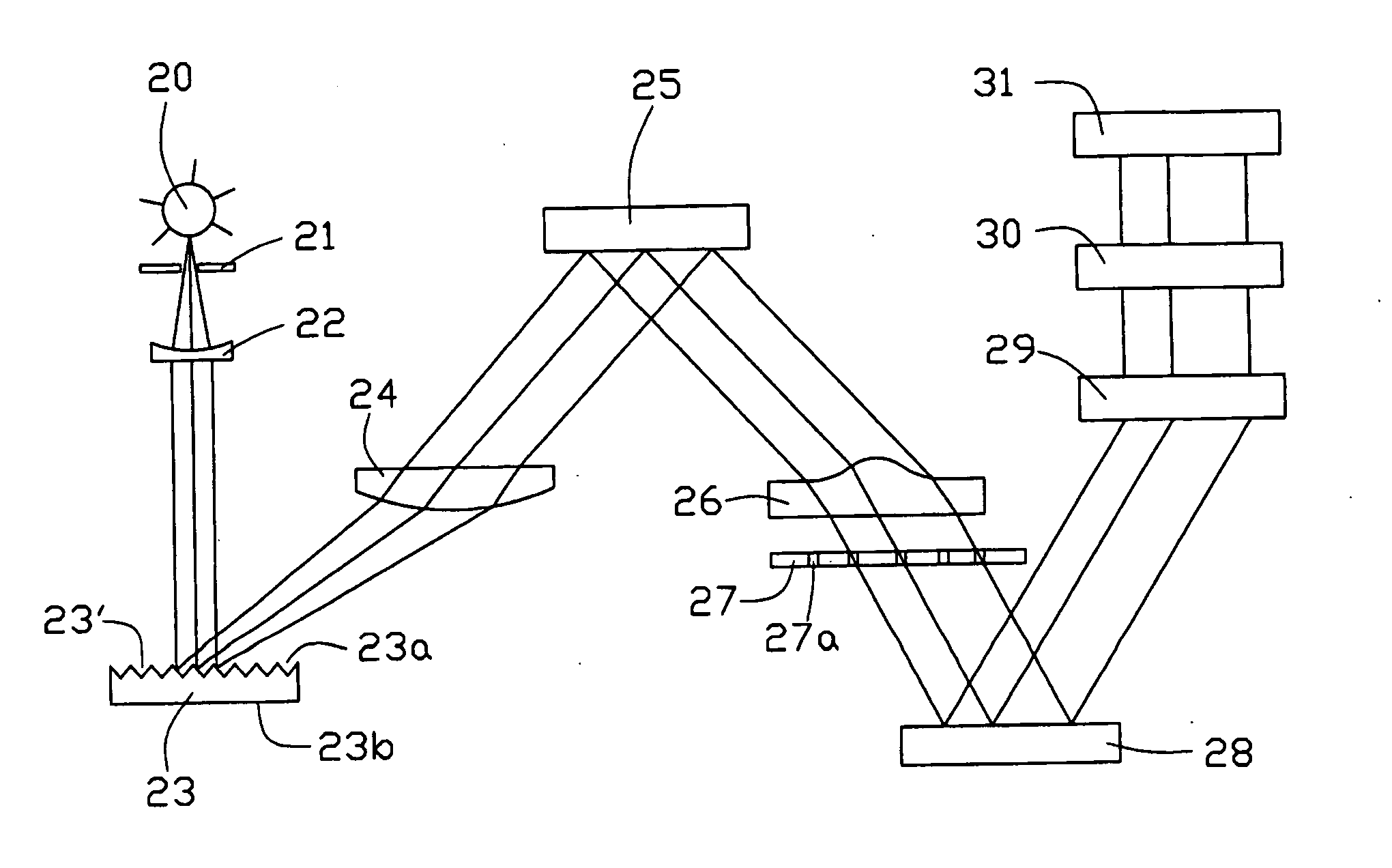
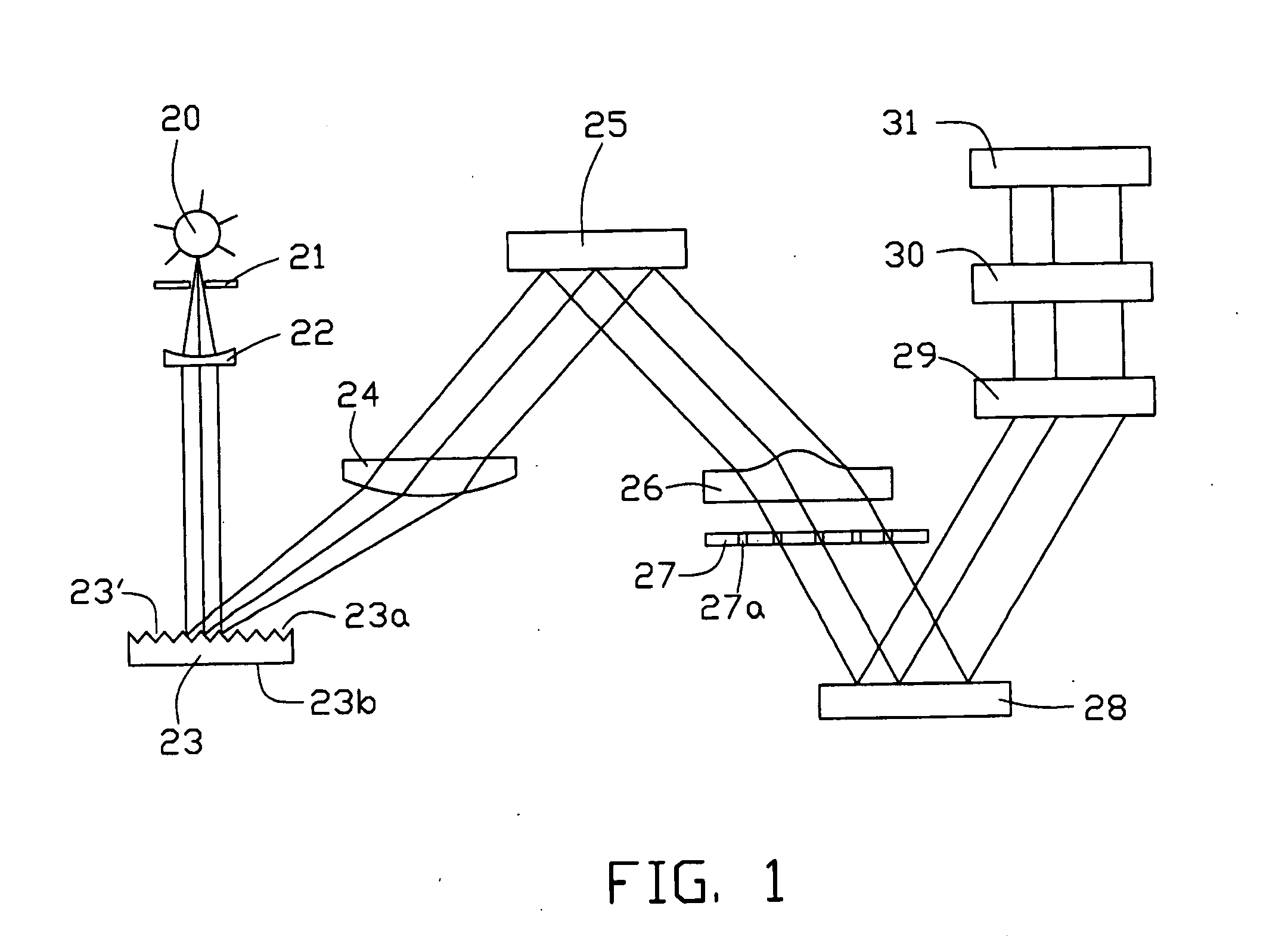
[0019] Referring to FIG. 1, a first embodiment provides an optical processor. The optical processor, typically for a spectrograph, includes a light source 20, a first slit plate 21, a collimator 22, a grating device 23, a first lens 24, a reflector 25, a second lens 26, a second slit plate 27, an array of mirror cells 28, a color wheel 29, a third lens 30 and a screen 31 all located along a continuous optical path. The light source 20 is an inductively-coupled-plasma source (ICP source) for emitting light beams. The ICP source has the advantages of satisfactory stability, high excitation temperature, wide linear range, and rare chemical interference. Alternatively, a laser source can be used as the light source 20.

[0020] The light beams enter the collimator 22 via the first slit plate 21. The first slit plate 21 is an entrance slit plate, and is positioned between the light source 20 and the collimator 22. The collimator 22 gathers the light beams from the first slit plate 21, and ...


PUM


Abstract

An optical processor includes a light source (20), a grating device (23), a first lens (24), a reflector (25), a second lens (26), an array of mirror cells (28), a color wheel (29), and a third lens (30). The light source is for generating a number of light beams. The grating device is for reflecting and dispersing the generated light beams. The first lens is for imaging the reflected and dispersed light beams. The reflector is for reflecting the imaged light beams. The second lens is for correcting any aberration of the reflected light beams. The array of mirror cells is for reflecting the light beams received from the second lens. The color wheel is for coloring the reflected light beams. The third lens is for projecting the colored light beams onto a display.

Description

FIELD OF THE INVENTION [0001] The present invention generally relates to optical processors used in devices such as precision instruments, and more particularly to a detecting assembly for an optical processor. BACKGROUND OF THE INVENTION [0002] Spectrum technology is a relatively new high-tech field which incorporates optics, spectroscopy, precision machinery, electronics technology and computer techniques. Spectrum technology assists a user to obtain plenty of information pertaining to a space or a spectrum. Because of this great advantage, spectrum technology has numerous applications in pursuits such as navigation, scientific experimentation, industrial manufacturing, agriculture, geology, oceanography, and safety devices. Similarly, spectrum technology already has a great reputation in the development of optical instruments. [0003] A spectrograph is an essential piece of equipment for performing spectrum analysis. Analyzing a spectrum can provide information about elements comp...

Claims


Application Information

Patent Timeline
IPC IPC(8): G01J3/28G01J3/40
CPCG01J3/02G01J3/0208G01J3/021G01J3/40G01J3/0232G01J3/0235G01J3/0229
Inventor CHEN, GA-LANE
Owner HON HAI PRECISION IND CO LTD
Learn More