Method of compressing a portion of a lung

a lung and compression technology, applied in the field of lung compression, can solve the problems of major airways not being suspended, major airways collapsing, affecting the effect of air flow,

Inactive Publication Date: 2006-01-12
EKOS CORP
View PDF58 Cites 184 Cited by
  • Summary
  • Abstract
  • Description
  • Claims
  • Application Information

AI Technical Summary

Problems solved by technology

Likewise, toxic CO2 is diffused into the alveoli from the capillaries and is removed from the body during expiration.
These stretched regions fail to pull on and thus fail to suspend the major airways in a radial fashion to hold them open.
As the disease progresses, the patient will eventually need to force expiration, which causes the major airways to collapse and block air flow.
This effect is exacerbated with additional applied expiration pressure since the airways are ill-supported.
Pain associated with this causes interruption of normal breathing and difficulty to revive the patient from forced ventilation to normal breathing after the procedure.
The procedure presents with high mortality rates and long recovery times.
Another risk with LVRS is associated with cutting too much volume out.
Also, adhesions between the lung and chest wall that occur naturally present stress points upon expansion that can cause ruptures.
The imbalance of force in the chest after expanding highly elastic lung tissue pulls the mediastinal region of the central thorax sufficiently to actually shift large vessels and cause flow restrictions.
This condition can be very serious and warrant further surgeries.
Current less invasive approaches to LVR have met with limited success, however.
However, there are several problems with these earlier devices as they are currently used.
Current blocking devices do not facilitate access to distal regions of the lung after deployment to allow for reoccurring interventions or treatments.
Covered devices that are stretched to this extent are typically not robust air leak seals.
This also requires that the device be scaled down to such a small diameter profile that the self expansion forces are extremely low to anchor the device and the covering materials must be thin and therefore fragile.
Moreover, these devices block air from flowing in the major airways but are not effective if collateral flow paths exist.
Finally, uncontrolled atelectasis beyond a one third volume reduction may cause tension pneumothorax complications and stress ruptures within the lung wall, causing lung collapse.

Method used


Image

  • Method of compressing a portion of a lung
  • Method of compressing a portion of a lung
  • Method of compressing a portion of a lung

Examples


Embodiment Construction

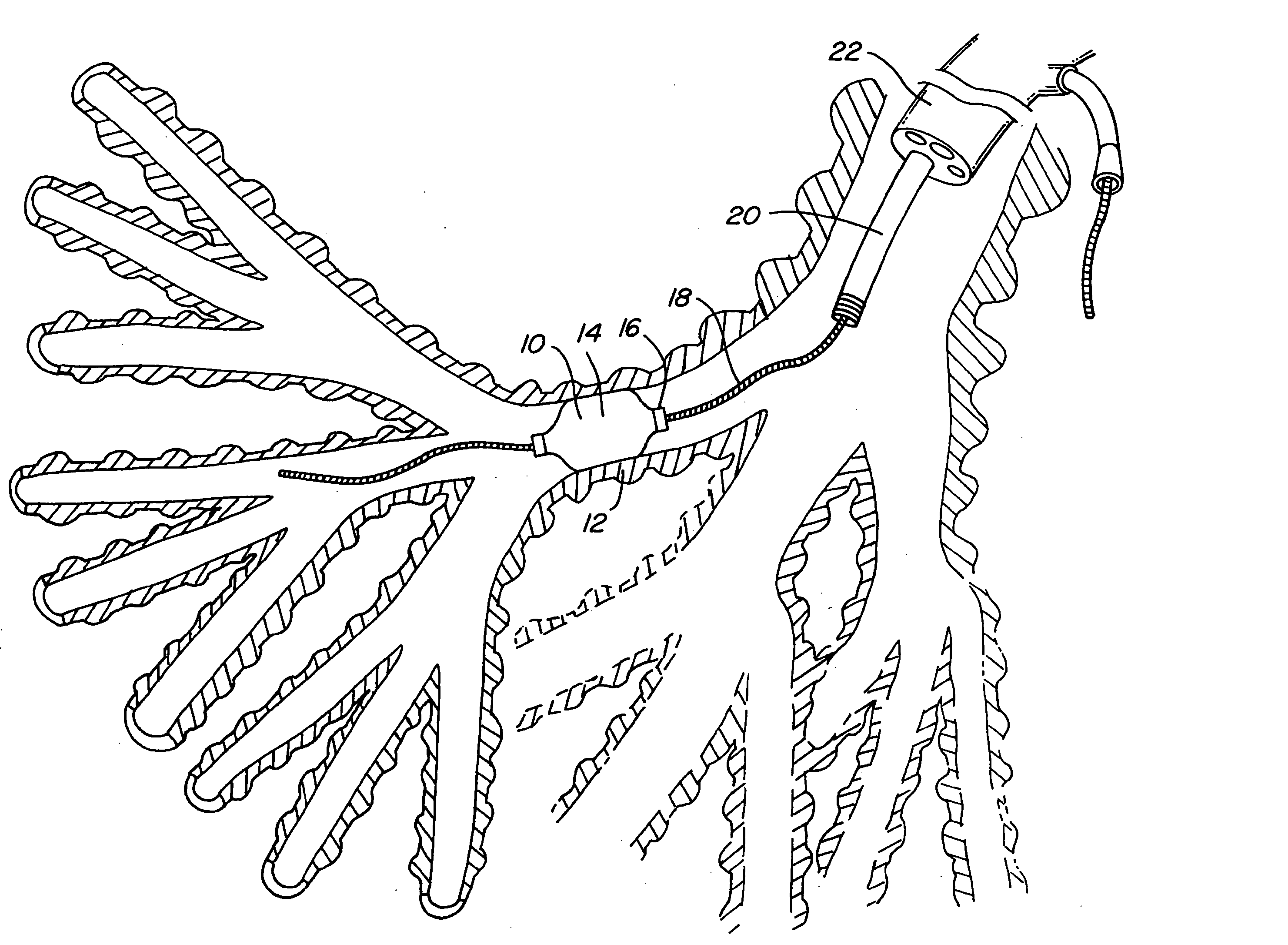
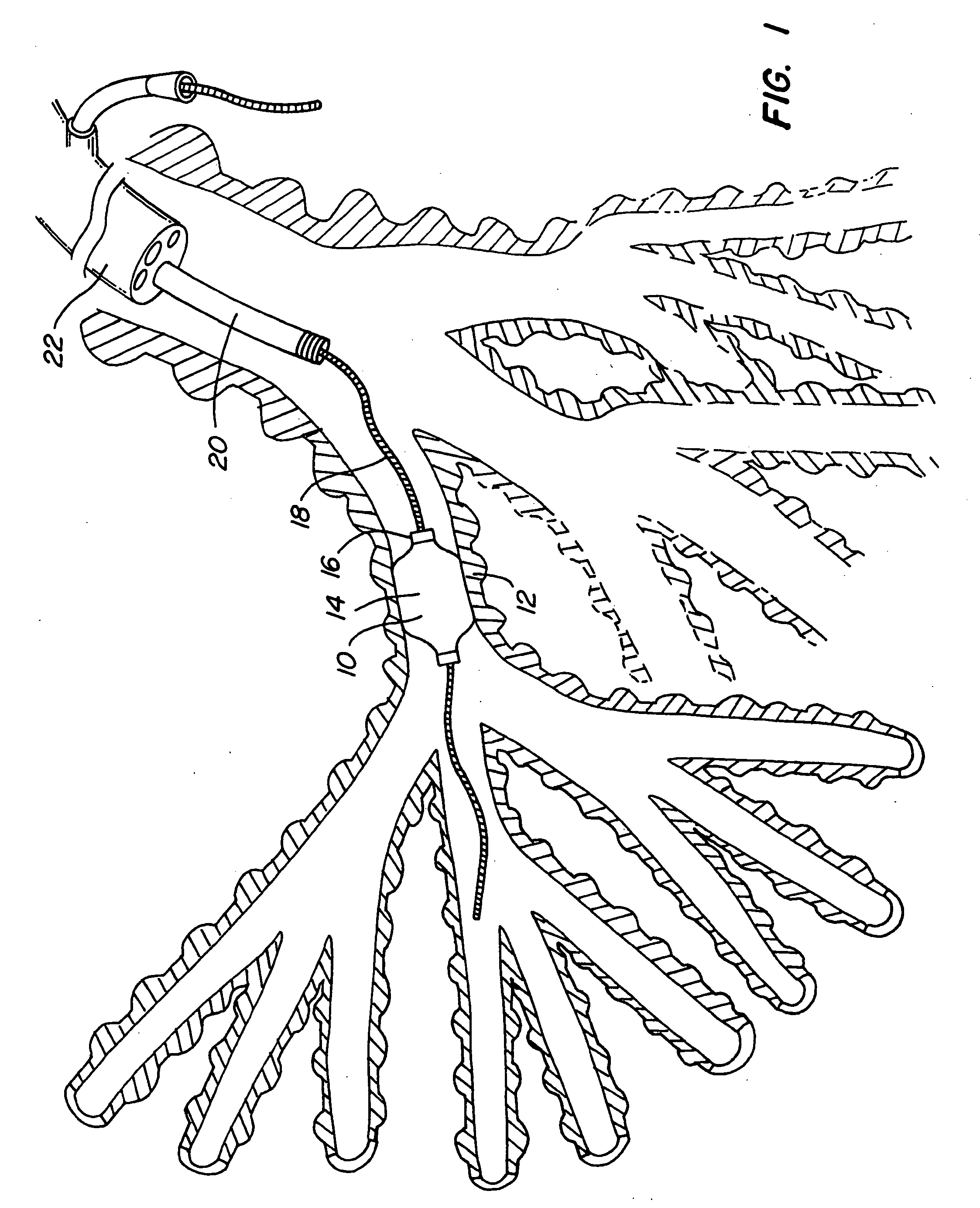
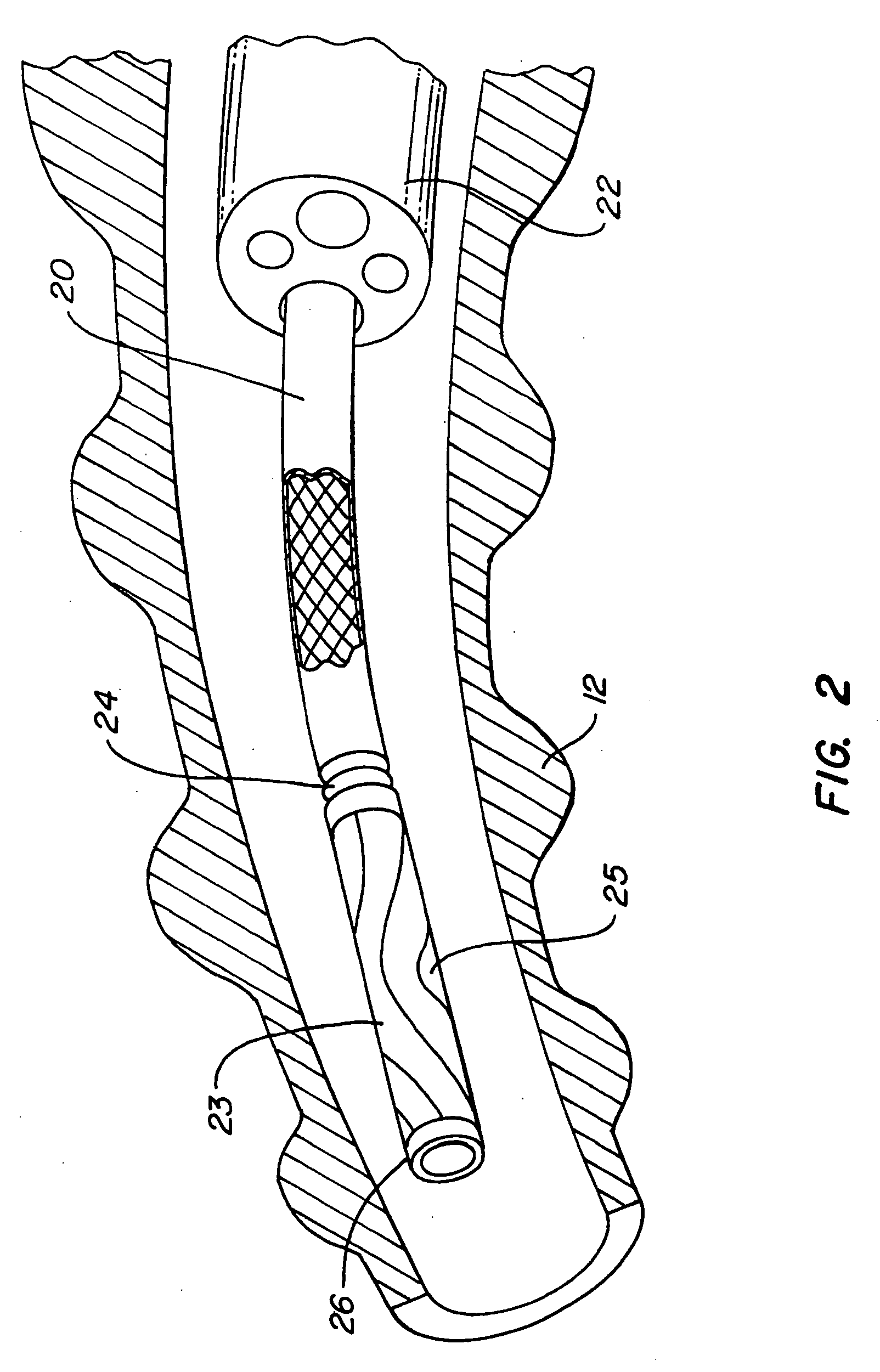
[0052] The following tools may be used to treat COPD patients in a minimally invasive manner: Imaging and embolic devices to block blood flow through the target lung tissue; devices to help prepare the lung for devices and agents; a side wire delivery system that is advanced alongside the bronchoscope to guide and release several implants without removing the scope; a lung volume reduction implant device (Intra-Bronchial Device or IBD) that is controllably coupled to a delivery catheter that includes a working channel that runs through the center of the catheter and the implant; an inflator catheter that fits down the middle of the IBD and delivery catheter to inflate the IBD; an IBD plug element and delivery system; a deflation device to reposition or remove the IBD; a collateral flow detecting device; collateral flow blocking agents; adhesion promoting agents to maintain atelectasis; and a lung tissue compressing system. These items provide a reliable minimally invasive procedure ...


PUM


Abstract

The invention provides methods of performing lung volume reduction to treat a patient. One aspect of the invention provides a method of compressing a first portion of a lung of a patient including the following steps: providing a vent connecting the first portion of the lung to the exterior of the patient; isolating the first portion of the lung from a second portion of the lung adjacent the first portion; and delivering pressurized fluid to the second portion of the lung to compress the first portion of the lung.

Description

CROSS-REFERENCE [0001] This application claims the benefit of U.S. Provisional Application No. 60 / 580,565, filed Jun. 16, 2004, which is incorporated herein by reference in its entirety.BACKGROUND OF THE INVENTION [0002] The primary role of the lung is to perform the function of breathing which assists in the intake of oxygen and removal of carbon dioxide from the body. The oxygen in air is inhaled through the mouth and trachea to the main bronchi. The bronchi divide at the end of the trachea into the left and right main bronchi and these respectively divide into bronchial branches, which “feed” the three lobes of the lung on the right and two on the left. These bronchi continue to subdivide into bronchioles (smaller bronchi), over twenty three times in total. The over 100,000 bronchioles get smaller in diameter and ultimately terminate in over 300 million air sacs, called alveoli. The alveoli, which are clustered like grapes, are approximately 0.3 mm in diameter and provide a huge ...

Claims


Application Information

Patent Timeline
Patent Type & Authority Applications(United States)
IPC IPC(8): A61M31/00A61B17/12A61B17/22A61B18/18A61M25/00A61M25/10A61M29/00
CPCA61M2210/1039A61B2017/12054A61B17/12136A61B17/12186A61B2017/22067A61M25/0026A61M25/0069A61M25/007A61M25/0075A61M25/10A61M25/1027A61M2025/1052A61M2025/1054A61B2017/12095A61B17/12104
Inventor MATHIS, MARK L.
Owner EKOS CORP
Why Eureka
Try Eureka