
Cleaner

a vacuum cleaner and self-propelled technology, applied in the field of vacuum cleaners, can solve the problems of large noise and consumption of electric power, and achieve the effects of suppressing power consumption and noise generation, preventing dust scattering from the side brush, and high dust collection property

Inactive Publication Date: 2006-01-19
SANYO ELECTRIC CO LTD
View PDF1 Cites 155 Cited by
  • Summary
  • Abstract
  • Description
  • Claims
  • Application Information

AI Technical Summary

Benefits of technology

The present invention is a self-propelled vacuum cleaner that can effectively collect dust while minimizing power consumption and noise. It uses a side brush for cleaning along walls and around obstacles, and a detection system to avoid unnecessary brush operation. The cleaner can also change its travel direction based on obstacle detection. Overall, the invention prevents dust scattering, cord tangling, and noise generation, resulting in improved cleaning efficiency and a better user experience.

Problems solved by technology

However, in such a conventional self-propelled vacuum cleaner, there arises a problem that an electric power is consumed and a large noise is generated all the more because the side brush is usually rotating during the cleaning.
However, there is a possibility that when the self-propelled vacuum cleaner travels in a place which does not have many obstacles such as a center of a room, the side brush scatters the dust about rather than collects the dust.

Method used


Image

  • Cleaner
  • Cleaner
  • Cleaner

Examples


Embodiment Construction

[0035] Hereinafter, an embodiment of the present invention will be described with reference to the accompanying drawings.

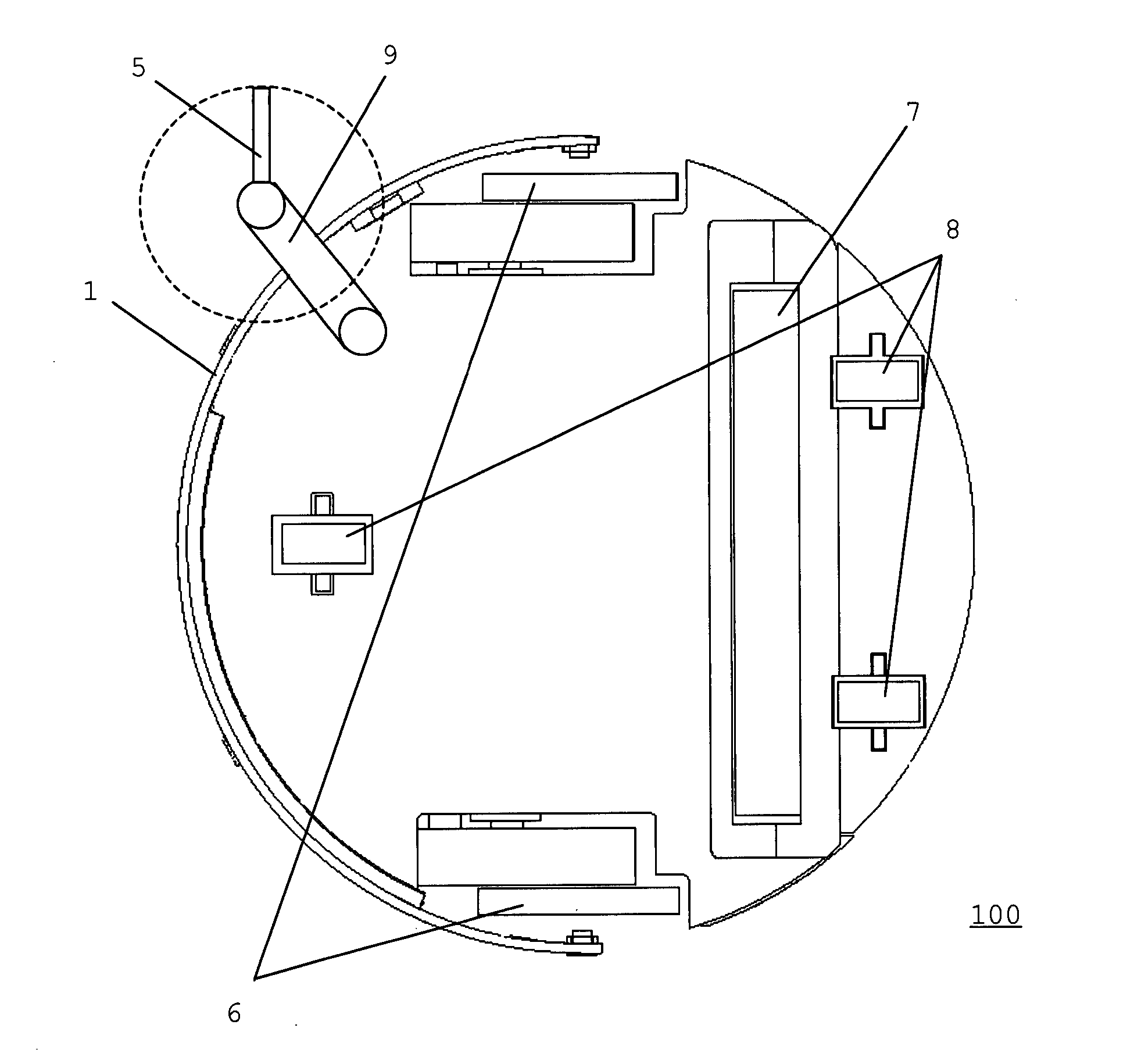
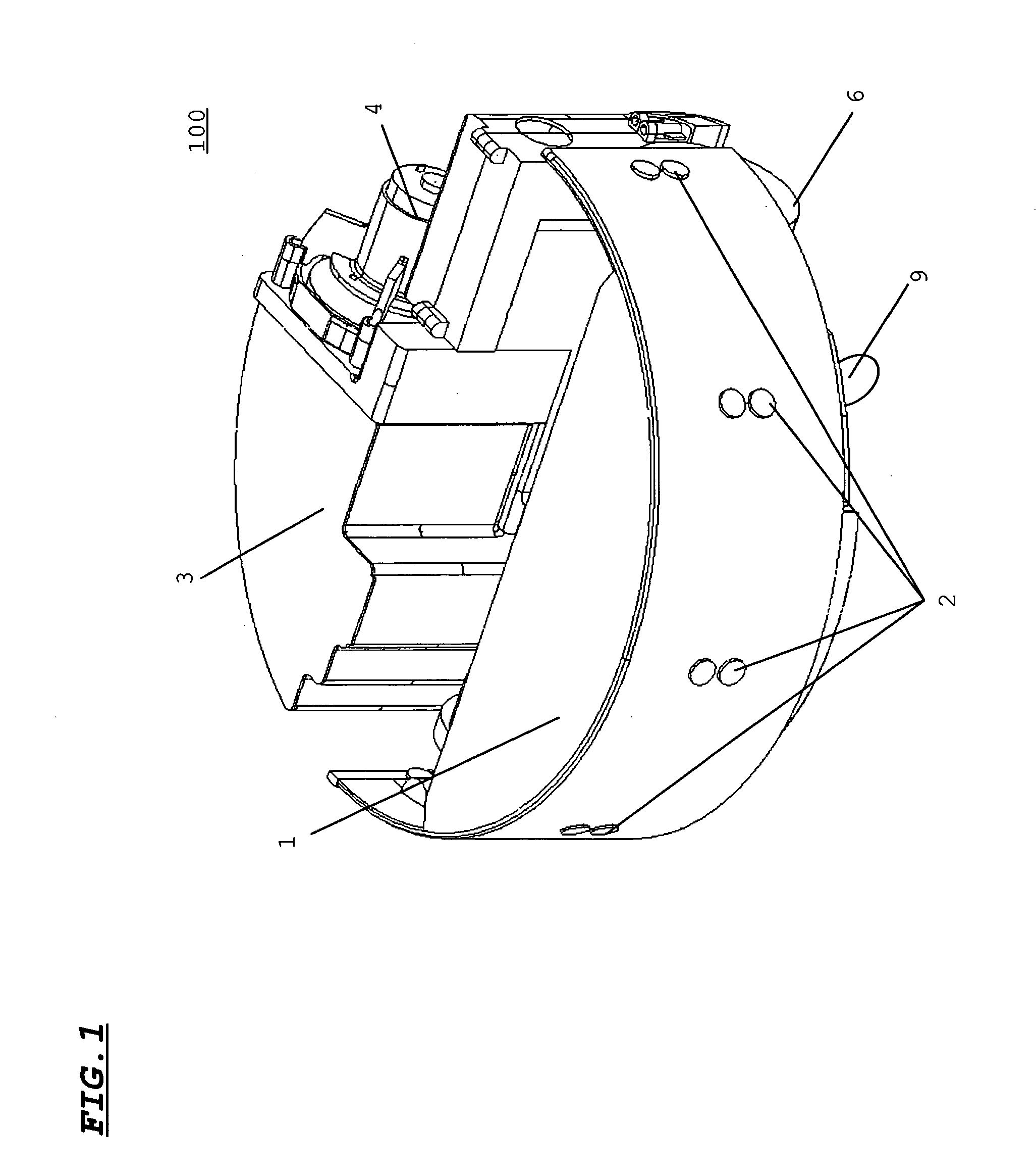
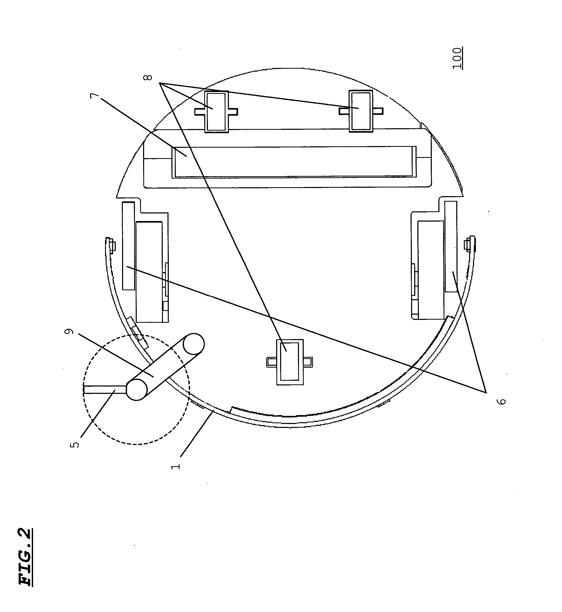
[0036]FIG. 1 is a perspective view of a cleaner 100 according to an embodiment of the present invention, and FIG. 2 is a bottom view of the cleaner 100 according to the embodiment of the present invention.

[0037] Referring to FIG. 1, reference numeral 1 designates a bumper; 2, an obstacle detecting sensor; 3, a dust collecting box; and 4, a fan motor for a dust collecting operation.

[0038] The bumper 1 doubles as a contact type sensor such as a switch for detecting, when an obstacle or the like unexpectedly contacts the cleaner 100, the unexpected contact. The bumper 1 functions as a sensor for carrying out a stoppage, a back operation, or the like of the cleaner 100 when, for example, a leg or the like of someone suddenly touches the cleaner 100.

[0039] The obstacle detecting sensor 2 is a non-contact type sensor such as an ultrasonic sensor for detecting an obs...


PUM


Abstract

Only when a wall side and the vicinity of an obstacle are cleaned, a side brush is operated and the cleaning is carried out, and when any other place than the wall side and the vicinity of the obstacle is cleaned, the side brush is maintained in a stoppage state. When a place such as the wall side or the vicinity of the obstacle in which dust is easy to accumulate is cleaned, the side brush is operated to enhance the dust collecting property. When any other place than the wall side or the vicinity of the obstacle is cleaned, the side brush is stopped to suppress power consumption and generation of a noise. A judgment processing portion detects based on a detection signal from an obstacle detecting portion that a cleaner is approaching a wall or an obstacle. In response to such detection, the judgment processing portion instructs a travel steering portion to carry out immediate rotation and change of a travel direction, or travel along a wall side. Also, the judgment processing portion instructs a side brush driving portion to drive a side brush only in the rotation and in the wall side travel, and to stop the side brush in straight advance travel.

Description

[0001] This application claims priority under 35 U.S.C. §119 of Japanese Patent Application No. 2004-207861 filed Jul. 14, 2004. BACKGROUND OF THE INVENTION [0002] 1. Field of the Invention [0003] The present invention relates to a cleaner, and more particularly to a self-propelled vacuum cleaner including auxiliary dust collecting means such as a side brush in addition to dust collecting means such as a dust collecting port or a suction nozzle. [0004] 2. Description of the Related Art [0005] In recent years, a so-called self-guided, self-propelled vacuum cleaner having a microcomputer and various sensors mounted therein has been developed and come into wide use. [0006] Normally, dust collecting means such as a suction nozzle or a brush is provided in a bottom portion of a main body of a self-propelled vacuum cleaner of this sort. During a self-guided, self-propelled operation, occasional travel positions are measured based on rotational frequencies of wheels and a travel direction....

Claims


Application Information

Patent Timeline
Patent Type & Authority Applications(United States)
IPC IPC(8): A47L5/00A47L9/00E01H1/08
CPCA47L9/009A47L2201/06A47L2201/04G05D1/0227A47L9/00A47L9/04A47L9/28
Inventor SHIMIZU, AKIONISHIKAWA, MASATO
Owner SANYO ELECTRIC CO LTD
Learn More