Heat-exchanger device and cooling system

Inactive Publication Date: 2006-01-19
OPTHERM - THERMAL SOLUTIONS
View PDF3 Cites 56 Cited by
  • Summary
  • Abstract
  • Description
  • Claims
  • Application Information

AI Technical Summary

Benefits of technology

[0086] Furthermore, in accordance with some preferred embodiments of the present invention, the syste

Problems solved by technology

The continuing reduction in size of microelectronic components, such as chips, diodes, laser sources and other su

Method used


Image

  • Heat-exchanger device and cooling system
  • Heat-exchanger device and cooling system
  • Heat-exchanger device and cooling system

Examples


Embodiment Construction

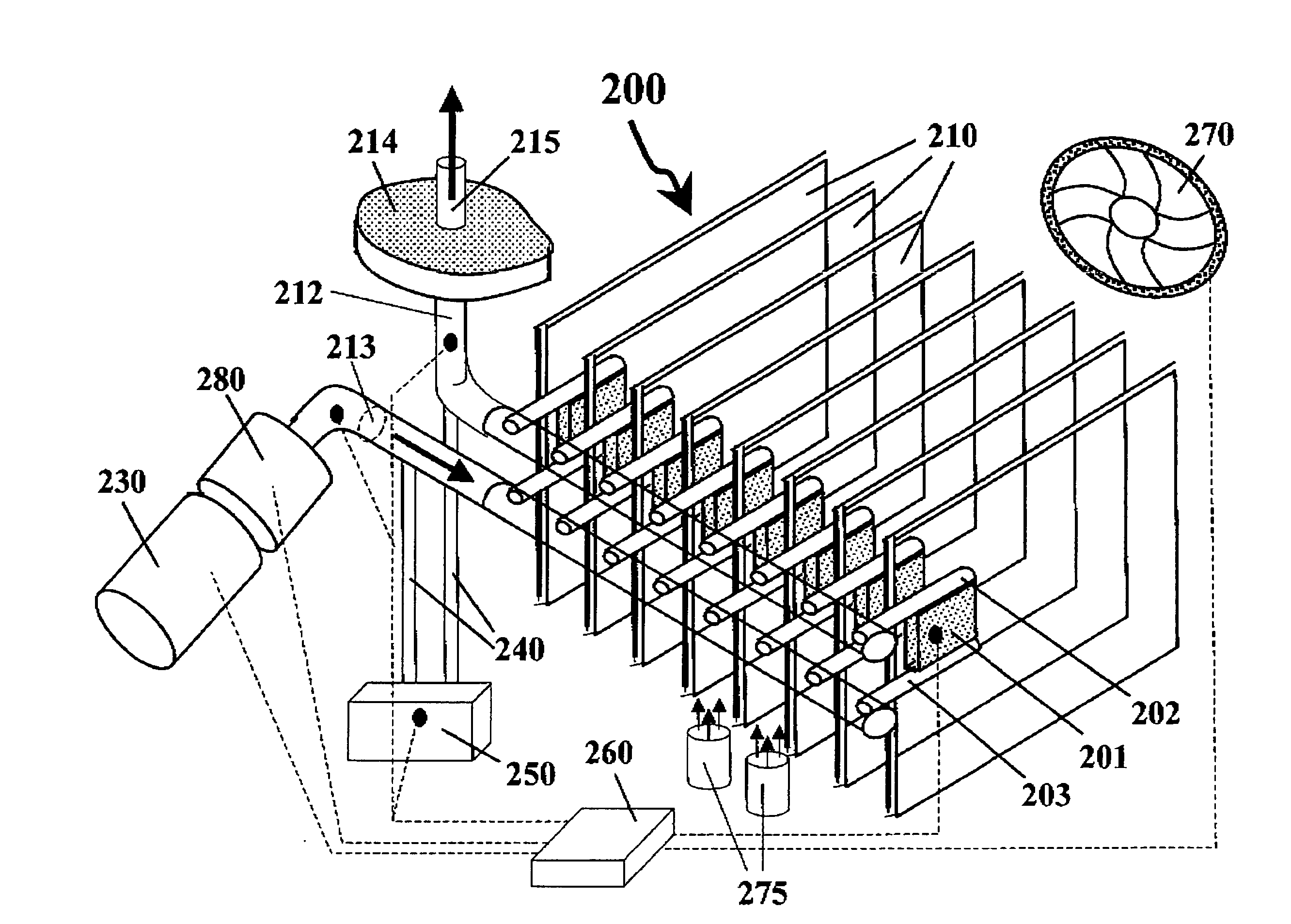
[0128] The present invention typically relates to a heat-exchanging device, aimed in particular at cooling electronic components (such as PC CPUs and main-frames or server's CPUs, electro-optic component that waste heat at small area and other general purpose heat-dissipating electronic components). Hereafter we shell refer only to cooling missions although the heat exchanger of the present invention may be implemented for heating missions too.

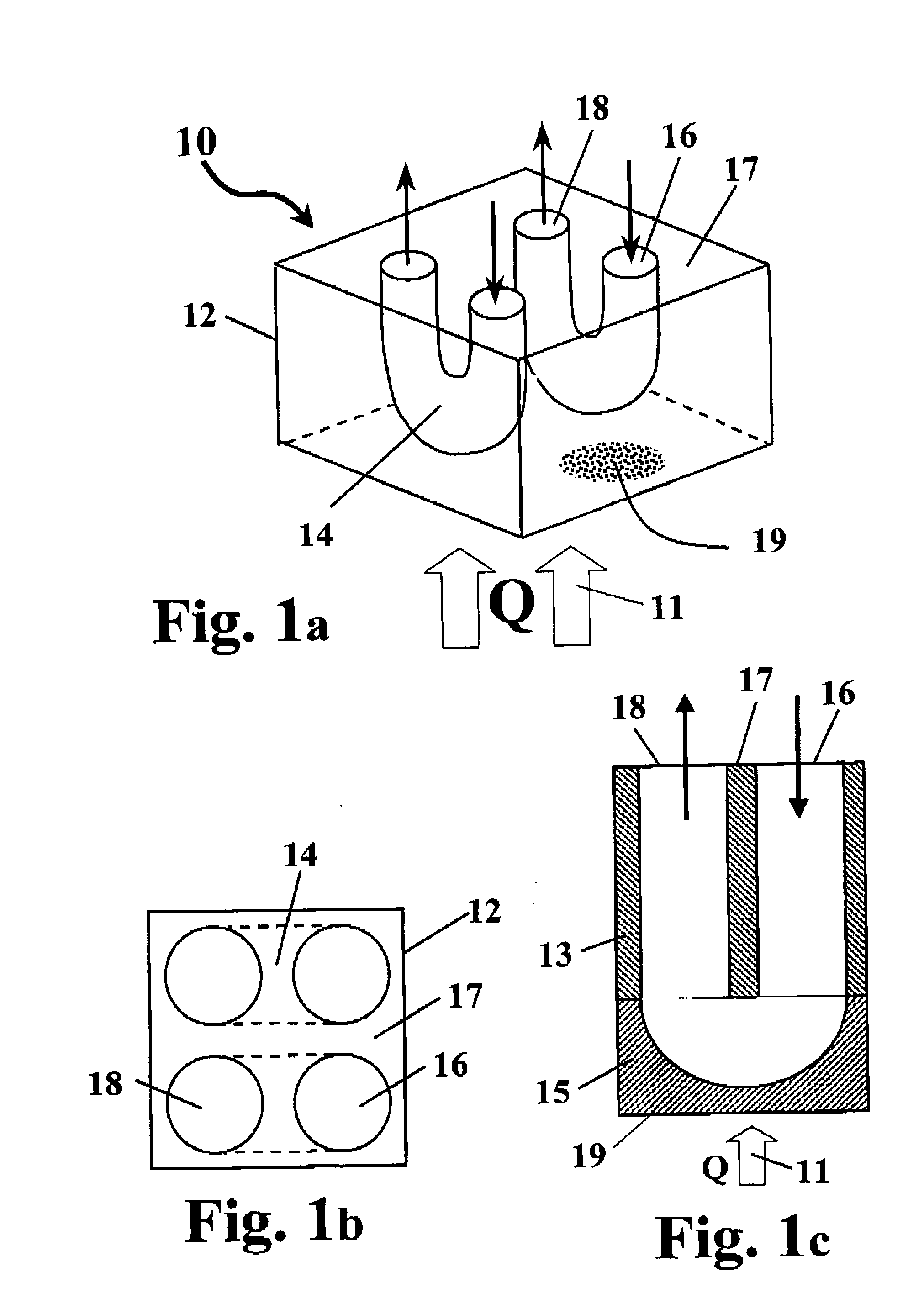
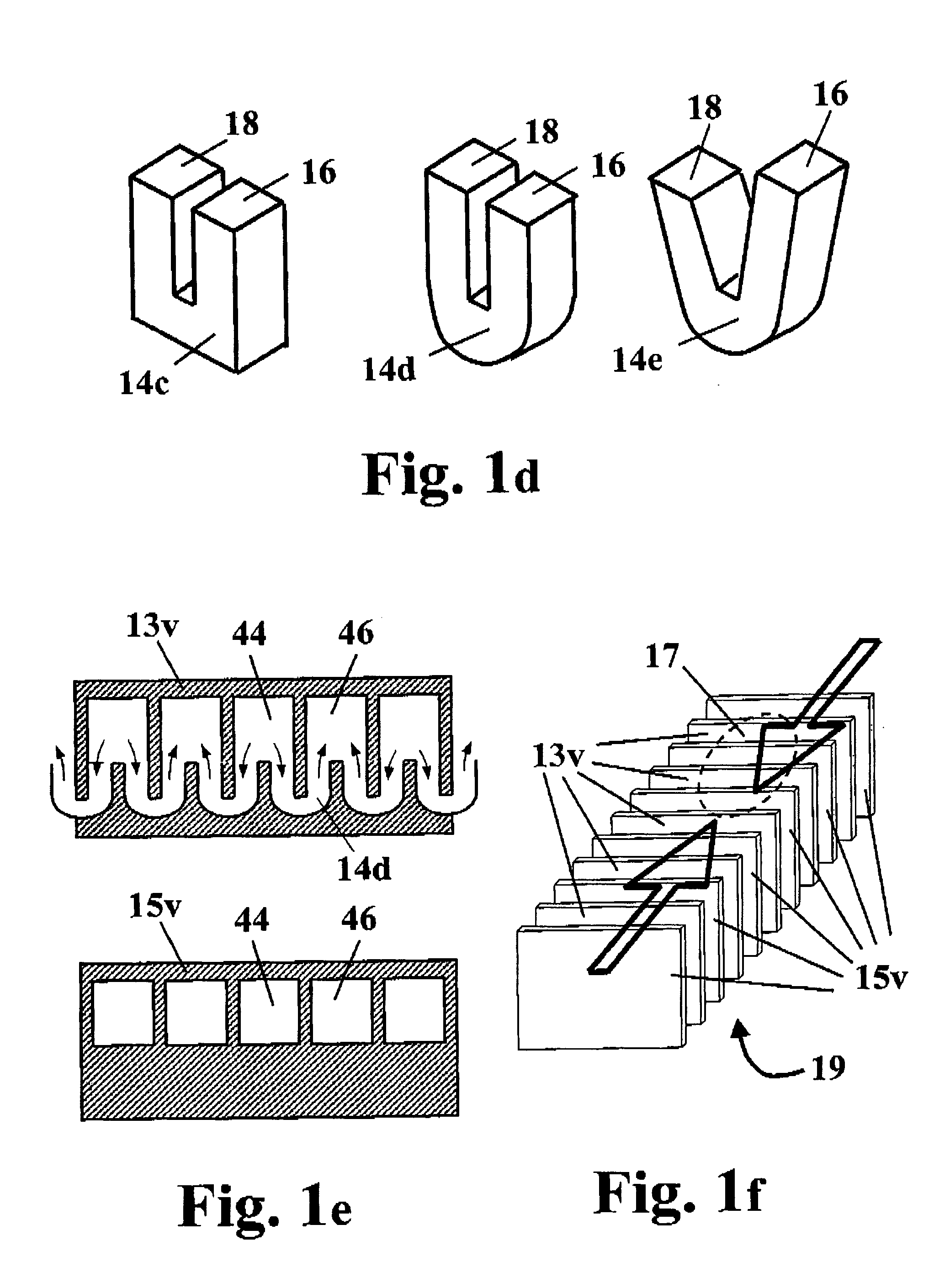
[0129] In principle, a heat-exchanging device in accordance with some preferred embodiments of the present invention comprises a block having at least two surfaces. One surface is subjected to a heat flux (to be refer to as the HT (heat-transfer) surface), for example by attaching it to a heat dissipating element, and a substantially opposite active surface. The block constitutes the heat exchanger body, and is made of a heat-conducting material with a plurality of small cooling tubes provided in it, each of the cooling tubes having an inlet ...


PUM


Abstract

A heat-exchanging device. The device comprises a block made from a heat-conducting material with a plurality of cooling tubes provided in it. Each of the cooling tubes has an inlet for receiving an inflow of a coolant fluid and an outlet for evacuating the coolant fluid, the inlet and the outlet of each cooling tubes are distributed on at least one active surface, which is substantially opposite a heat-transfer surface of the heat-exchanging device. Each cooling tube is designed to direct the coolant fluid towards and then away from said at least one heat-transfer surface. When subjected to a heat flux through the heat-transfer surface and when coolant fluid passes through the cooling tubes it absorbs heat from the block and evacuates it away.

Description

FIELD OF THE INVENTION [0001] The present invention relates to cooling (or heating) systems. More particularly the present invention relates to a heat-exchanging device. BACKGROUND OF THE INVENTION [0002] The continuing reduction in size of microelectronic components, such as chips, diodes, laser sources and other such devices, and the reduction in transistor rise time, presents a formidable challenge to the packaging industry. In order to facilitate effective near term utilization of the future microelectronic devices, the design and performance of first and second level packaging need a significant improvement with respect to the current state-of-the-art technology. Heat fluxes of various microelectronic devices exceeding 100 Watts per cm2 are currently considered in the art. [0003] Various solutions for cooling microelectronic devices have been suggested in the literature and are known in the art. The following are examples of air cooling systems. [0004] In U.S. Pat. No. 4,447,84...

Claims


Application Information

Patent Timeline
IPC IPC(8): H05K7/20
CPCF28D1/0475F28D1/0476F28D2021/0029F28F7/02H01L23/473H01L2924/1461H01L2224/73253H01L2924/00
Inventor YUVAL, YASSOUR
Owner OPTHERM - THERMAL SOLUTIONS
Why Eureka
Try Eureka