

Damper for damping vibration and washing machine having the same
a technology of damper and damper cylinder, which is applied in the direction of spring/damper, other washing machines, textiles and paper, etc., can solve the problems of increasing vibration and noise, increasing the friction force as time goes, etc., and achieves the effect of increasing the friction force between the friction member and the inner wall of the damper cylinder
- Summary
- Abstract
- Description
- Claims
- Application Information
AI Technical Summary
Benefits of technology
Problems solved by technology
Method used
Image

Examples
first embodiment
[0076] First, with reference to FIGS. 4 to 8, a damper in accordance with the present invention will be described.
[0077] Here, FIG. 4 is a sectional view of the damper in accordance with the first embodiment of the present invention. FIGS. 5A and 5B are a partial and longitudinal sectional view and a transversal sectional view illustrating a friction member of the damper shown in FIG. 4, which is separated from the inner wall of a damper cylinder. FIGS. 6A and 6B are a partial and longitudinal sectional view and a transversal sectional view illustrating the friction member of the damper shown in FIG. 4, which contacts the inner wall of the damper cylinder. FIG. 7 is a sectional view of another embodiment of a pressure unit of the damper of the present invention. FIG. 8 is a perspective view of yet another embodiment of the pressure unit of the damper of the present invention.
[0078] The damper of the present invention, which will be described hereinafter, may be applied to general w...
second embodiment
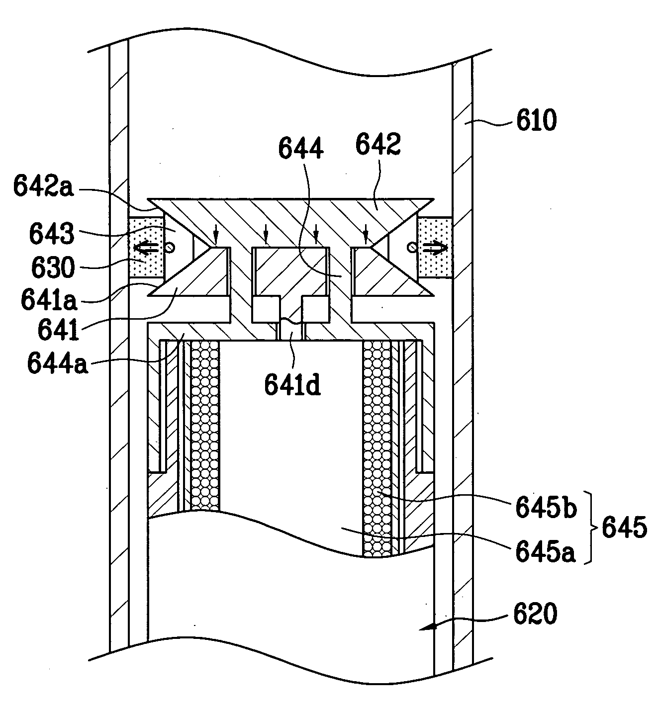
[0142] First, a damper 600a in accordance with the present invention will be described with reference to FIGS. 9A and 9B.
[0143] With reference to FIGS. 9A and 9B, the damper 600a comprises a connection rod 744 passing through the first pressure member 641 and the second pressure member 642 and vertically moving.
[0144] For this reason, vertical guide holes (not shown) are respectively formed through central portions of the first and second pressure members 641 and 642.
[0145] Here, the diameter of the guide holes formed through the first and second pressure members 641 and 642 is larger than that of the connection rod 744.
[0146] The lower end of the connection rod 744 is connected to an actuator (not shown), and is connected to a wire 745 for drawing the connection rod 744 downwardly.
[0147] A head 744a having a diameter larger than that of the guide hole of the second pressure member 642 is formed on the upper end of the connection rod 744.
[0148] Accordingly, when the wire 745 dr...
third embodiment
[0152] Hereinafter, a damper 600b in accordance with the present invention will be described with reference to FIGS. 10A and 10B.
[0153] With reference to FIGS. 10A and 10B, the damper 600b comprises a connection rod 844 passing through the first pressure member 641 and connected to the second pressure member 642 in order to vertically move the second pressure member 642.
[0154] More specifically, the connection rod 844 vertically passes through the second pressure member 642.
[0155] For this reason, vertical guide holes (not shown) are respectively formed through central portions of the first and second pressure members 641 and 642.
[0156] Particularly, a female screw thread is formed in the guide hole of the second pressure member 642, and a male screw thread corresponding to the female screw thread is formed on the outer cylindrical surface of the connection rod 844. The female screw thread of the guide hole of the second pressure member 642 is engaged with the male screw thread o...
PUM
 Abstract
Description
Claims
Application Information