Separation apparatus, method of fabricating the same, and analytical system

a technology of separation apparatus and apparatus, applied in the direction of electrolysis, diaphragm, chemical vapor deposition coating, etc., can solve the problems of difficult to fully reduce the gaps between obstacles, and the likelihood of damage of obstacles, and achieve excellent resolution

Inactive Publication Date: 2006-01-19
NEC CORP
View PDF5 Cites 29 Cited by
  • Summary
  • Abstract
  • Description
  • Claims
  • Application Information

AI Technical Summary

Benefits of technology

[0008] The present invention was conceived after considering the above-described situation, and an object thereof resides in providing a separation technique capable of separating a sample containing substances of various sizes with an excellent resolution. It is another object of the present invention to provide a separation technique capable of separating a sample containing substances of various sizes within a short time. It is another object of the present invention to provide a separation technique capable of reducing costs for separating a sample containing substances of various sizes. It is another object of the present invention to provide a technique capable of stably fabricating a separation apparatus used for separating a sample containing substances of various sizes.
[0053] The present invention can therefore separate the sample containing substances of various sizes with an excellent resolution.

Problems solved by technology

It has, however, been difficult for this technique to precisely fabricate such a large number of obstacles while ensuring small gaps therebetween, so that it has consequently been difficult to fully reduce the gaps between the obstacles.
It has also been known that the configuration, in which a large number of fine obstacles are arranged in a matrix pattern, raises another problem in that the obstacles are likely to be damaged in the formation process or during use of the separation apparatus.

Method used


Image

  • Separation apparatus, method of fabricating the same, and analytical system
  • Separation apparatus, method of fabricating the same, and analytical system
  • Separation apparatus, method of fabricating the same, and analytical system

Examples


first embodiment

(First Embodiment)

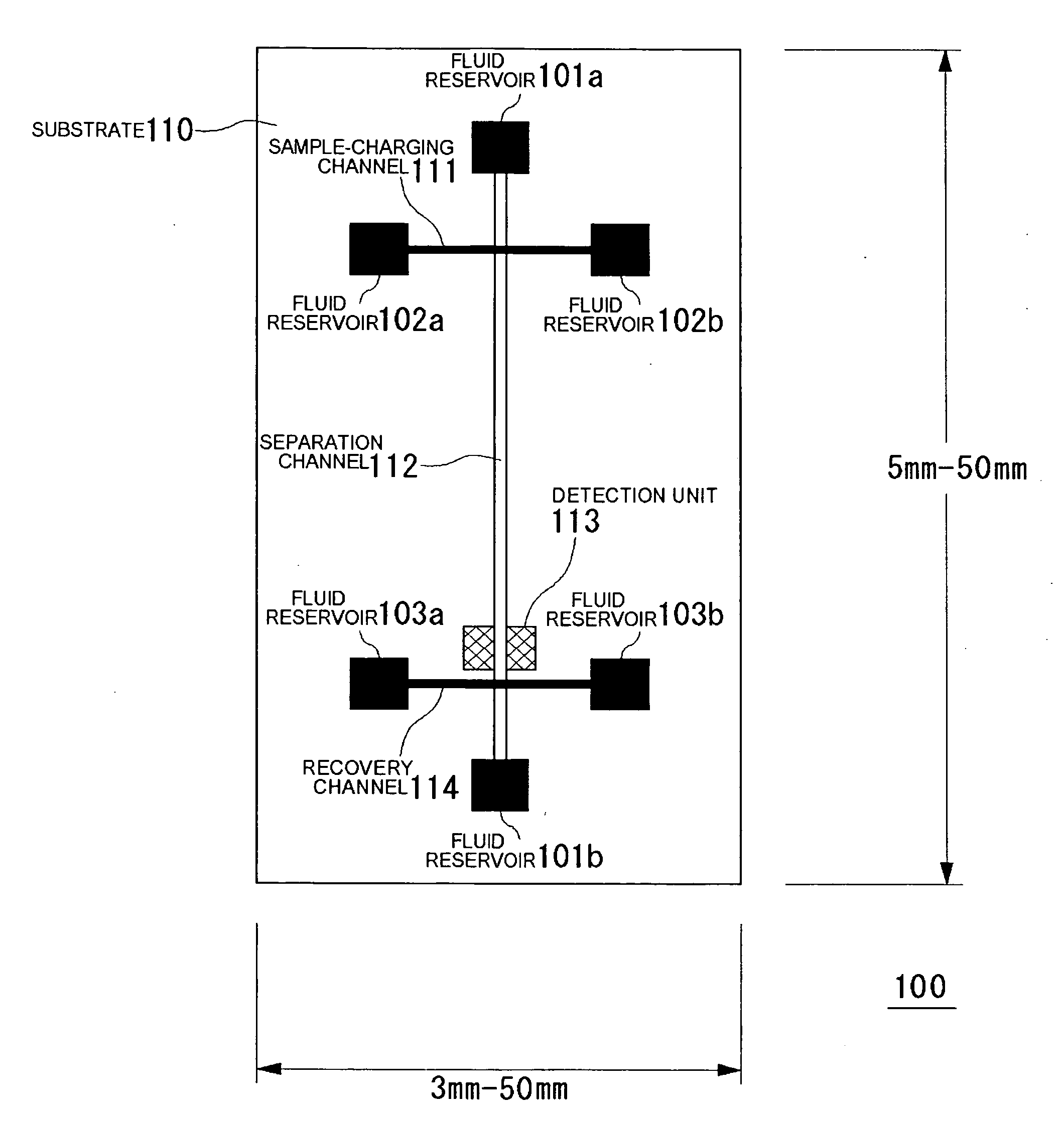
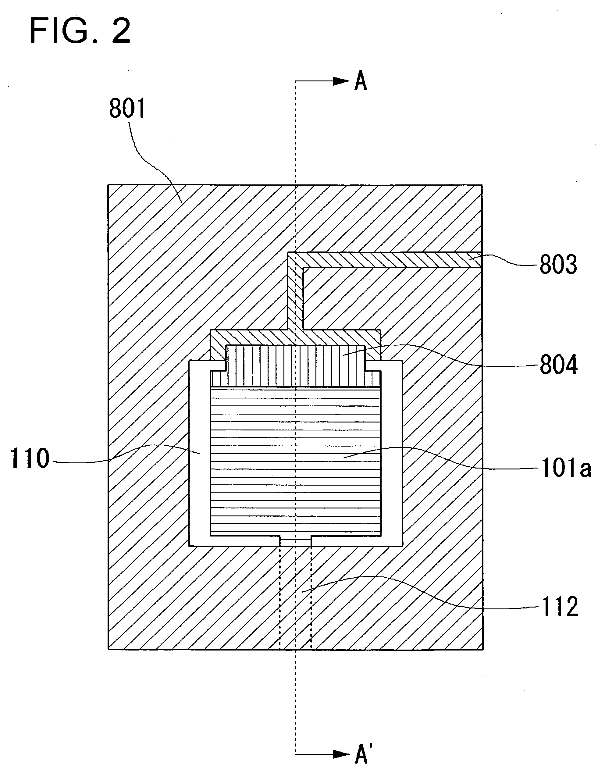
[0107]FIG. 1 is a drawing showing an exemplary separation apparatus according to a first embodiment of the present invention.

[0108] A separation channel 112 is formed on a substrate 110, and a sample-charging channel 111 and a recovery channel 114 are formed so as to cross therewith. The sample-charging channel 111, separation channel 112 and recovery channel 114 have, on their both ends, a fluid reservoir 102a, a fluid reservoir 102b, a fluid reservoir 101a, a fluid reservoir 101b, a fluid reservoir 103a and a fluid reservoir 103b, respectively. Each of these fluid reservoirs has an electrode provided thereto, with which an electric field can be applied on both ends of each of the sample-charging channel 111, separation channel 112, and recovery channel 114.

[0109] The separation channel 112 has a detection unit 113 provided thereto. The outside dimension of the apparatus can appropriately be selected depending on the purpose of use, wherein it is generally selec...

second embodiment

(Second Embodiment)

[0171]FIG. 21 is a top view detailing a structure of the separation channel 112 according to this embodiment. A general configuration of the separation apparatus of this embodiment is similar to that of the separation apparatus 100 shown in FIG. 1. Also in this embodiment, similarly to the separation channel 112 in the first embodiment, the separation channel 112 has two partition wall 301a and partition wall 301b provided thereto. The partition wall 301a and partition wall 301b are respectively formed so as to have a plurality of capture portions 300, wherein the opening ratio (opening width / depth) of the capture portions 300 increases in the advancing direction of flow in the separation channel 112. Also in this embodiment, the partition wall 301a and partition wall 301b are formed by a series of a plurality of columnar structures 302a, 302b and 302c. The columnar structures 302a, 302b and 302c are square poles each having a rhombic bottom plane. The columnar st...

third embodiment

(Third Embodiment)

[0175]FIG. 23 is a top view detailing a structure of the separation channel 112 according to this embodiment. A general configuration of the separation apparatus of this embodiment is similar to that of the separation apparatus 100 shown in FIG. 1. Also in this embodiment, similarly to the separation channel 112 in the first embodiment, the separation channel 112 has two partition wall 301a and partition wall 301b provided thereto. Also the partition wall 301a and partition wall 301b herein are respectively composed of a plurality of columnar structures 302, and consequently have a plurality of capture portions 300. In this embodiment, the partition wall 301a and partition wall 301b are differed from those in the first embodiment and second embodiment, in that they have a plurality of communication portions 303 formed thereto. This allows communication of the channel between the partition wall 301a and partition wall 301b, the channel between the partition wall 301...


PUM

PropertyMeasurementUnit
thicknessesaaaaaaaaaa
depthaaaaaaaaaa

Abstract

A separation apparatus (100) has a separation channel (112), a partition wall (301a) and a partition wall (301b), wherein each of the partition wall (301a) and the partition wall (301b) has a capture portion (300) formed thereon. Molecules having a size acceptable by the capture portions (300) provided on the partition wall (301a) and the partition wall (301b) are captured by the capture portion (300) and reduced in the travel speed through the separation channel (112), and this makes it possible to precisely separate the sample depending on the molecular size.

Description

BACKGROUND OF THE INVENTION [0001] 1. Field of the Invention [0002] The present invention relates to an apparatus and a method of separating samples, and more particularly to an apparatus and a separation method preferably applicable to fine-scale separation of substances including nucleic acid fragments of various sizes, such as cell and nucleic acid fragment; organic molecules such as amino acid, peptide and protein; metal ion, colloid and latex bead. [0003] 2. Description of the Related Art [0004] Analyses of biological substances such as cell, nucleic acid and protein need preliminarily separation and purification of samples, or preliminarily isolation based on their sizes and electric charges. For example, the dideoxy method (Sanger method) is widely used for determining base sequence of DNA. In the process of synthesizing a complementary DNA by the Sanger method using a target single-strand DNA as a template, Taq polymerase and four kinds of deoxyribonucleotides, a single kind...

Claims


Application Information

Patent Timeline
Patent Type & Authority Applications(United States)
IPC IPC(8): C02F11/00G01N27/27B01D57/02B01J20/281B01L3/00B81C1/00G01N27/447G01N30/02G01N30/88G01N35/08G01N37/00
CPCB01L3/502746B01L3/502753B01L2300/0681B01L2400/086Y10T29/49002G01N27/44773G01N30/02G01N27/44704B01D15/34
Inventor SANO, TORUBABA, MASAKAZUIIDA, KAZUHIROKAWAURA, HISAOIGUCHI, NORIYUKISAKAMOTO, TOSHITSUGUHATTORI, WATARUSOMEYA, HIROKO
Owner NEC CORP
Why Eureka
Try Eureka