Fuel injector provided with a servo leakage free valve

a technology of servo-piston and fuel injector, which is applied in the direction of fuel injection apparatus, spraying apparatus, feeding system, etc., can solve the problems of reducing the efficiency of the system, requiring a long guidance length of sealing gap, and forming leakage gaps between the control chamber of the servo-piston

Inactive Publication Date: 2006-01-19
ROBERT BOSCH GMBH
View PDF15 Cites 7 Cited by
  • Summary
  • Abstract
  • Description
  • Claims
  • Application Information

AI Technical Summary

Benefits of technology

[0006] The servo-valve embodied in the form of a 3 / 2-way valve can be embodied in the form of a double seat valve. To that end, the valve is embodied with a one-piece servo-valve piston and with a multi-part valve body. Providing a sealing seat on the servo-valve makes it possible to compensate for an axial offset of a multi-part servo-valve housing. The proposed design of the 3 / 2-way servo-valve in the form of a double seat valve can avoid the wear and tolerance problems that occur when using slider seals that have small overlap lengths. The easy access to the valve seats facilitates manufacture.

Problems solved by technology

Although embodying the metering valve in the form of a 3 / 2-way servo-valve does achieve a simplified, inexpensive manufacture, it is disadvantageous that a leakage gap forms between the control chamber of the servo-piston of the servo-valve and a return line when the fuel injector is idle.
The actuation fluid flowing out through the leakage gap decreases the efficiency of the system and requires that the sealing gap be provided with a long guidance length.
A long guidance length of the sealing gap in turn requires a long structural length of the valve body of the servo-valve, which is undesirable in terms of available installation space since the aim is to produce a fuel injector that has an integrated pressure booster and is as compact as possible.

Method used


Image

  • Fuel injector provided with a servo leakage free valve
  • Fuel injector provided with a servo leakage free valve
  • Fuel injector provided with a servo leakage free valve

Examples


embodiment

VARIANTS

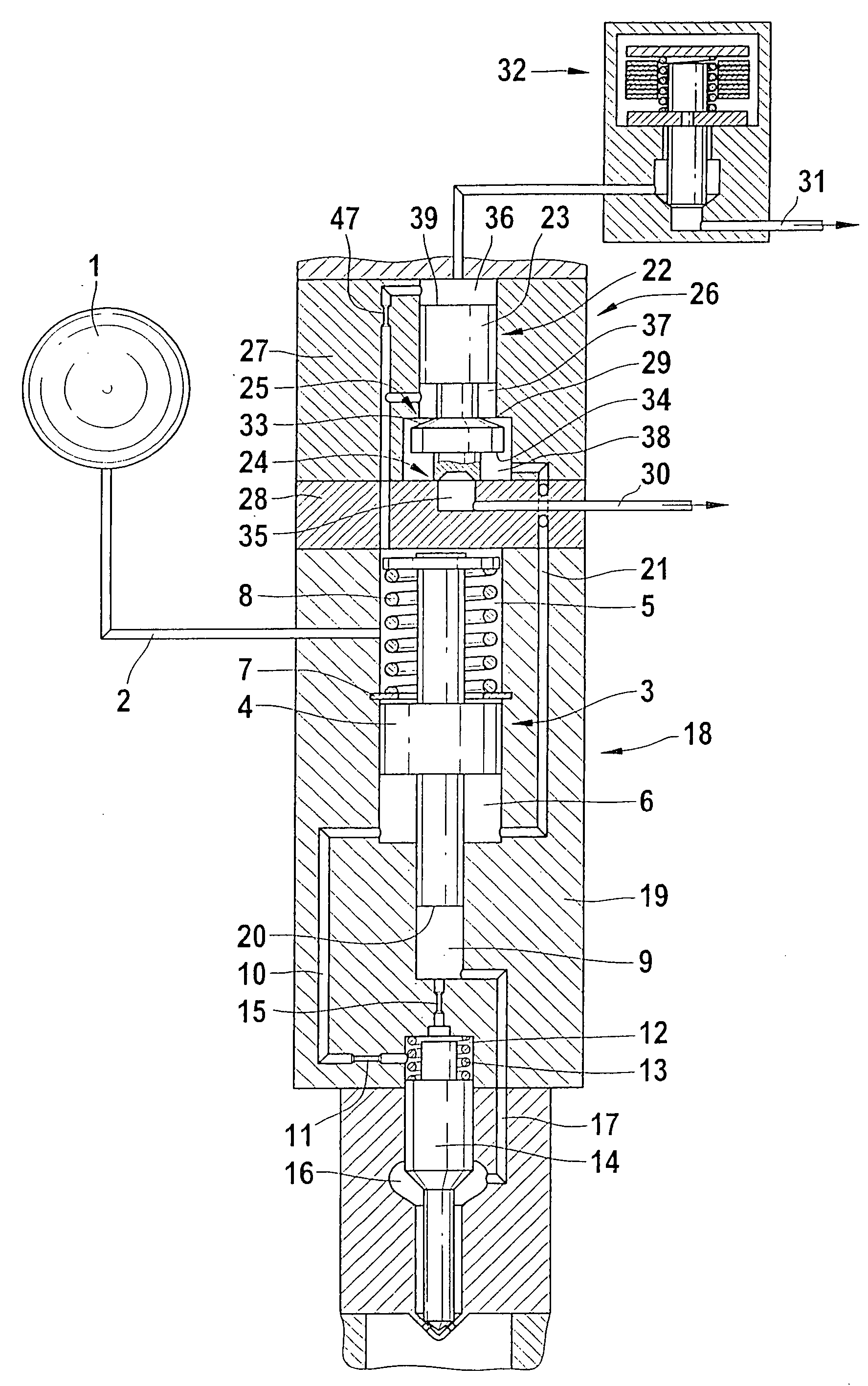
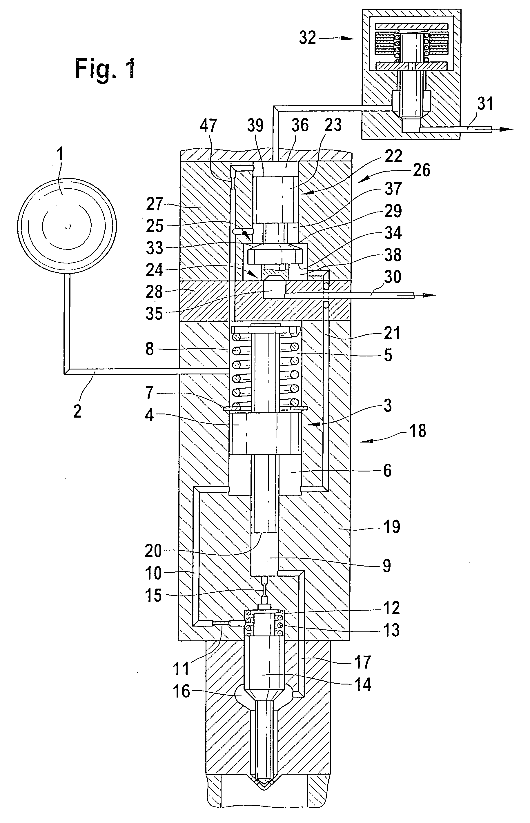
[0010] A pressure source 1, which can be embodied in the form of a high-pressure accumulator of a fuel injection system, acts on a high-pressure line 2 with highly pressurized fuel. The high-pressure line 2 feeds into a working chamber 5 of a pressure booster 3. The working chamber 5 is continuously acted on with the highly pressurized fuel of the pressure source 1. The working chamber 5 of the pressure booster 3 is separated from a differential pressure chamber 6 (return chamber) of the pressure booster 3 by a booster piston 4. The booster piston 4 of the pressure booster 3 is acted on by a return spring 8 that rests against a backup washer 7, which in turn is accommodated in an injector body 19 of the fuel injector 18. The booster piston 4 of the pressure booster 3 acts on a compression chamber 9 of the pressure booster 3. The end of the booster piston 4 oriented toward the compression chamber 9 has an end surface 20 which, when the pressure booster 3 is activated, travels...


PUM


Abstract

A fuel injector having a pressure booster whose booster piston separates a working chamber, which is continuously acted on with fuel by means of a pressure source, from a differential pressure chamber that can be pressure-relieved; a pressure change in the differential pressure chamber occurs via an actuation of a servo-valve whose control chamber can be pressure-relieved by an on / off valve that also opens or closes a hydraulic connection of the differential pressure chamber to a first return on the low-pressure side. In the deactivated state of the pressure booster, a first sealing seat seals a return on the low-pressure side off from a high-pressure region of the servo-valve, which region is comprised of the control chamber, a first hydraulic chamber, and a second hydraulic chamber.

Description

TECHNICAL FIELD [0001] Stroke-controlled injection systems with a high-pressure accumulator are used to deliver fuel in direct-injecting internal combustion engines. The advantage of these injection systems lies in the fact that the injection pressure can be adapted to wide ranges of load and engine speed. A high injection pressure is required in order to reduce emissions and to achieve a high specific output. Since the achievable pressure level in high-pressure fuel pumps is limited for strength reasons, pressure boosters are used in the fuel injectors in order to further increase pressure in fuel injection systems. PRIOR ART [0002] DE 101 23 913 relates to a fuel injection apparatus for internal combustion engines, having a fuel injector that can be supplied from a high-pressure fuel source. A pressure boosting device that has a movable pressure booster piston is connected between the fuel injector and the high-pressure fuel source. The pressure booster piston divides a chamber th...

Claims


Application Information

Patent Timeline
Patent Type & Authority Applications(United States)
IPC IPC(8): F02M41/16F02M47/02F02M57/02F02M59/10F02M59/46F02M61/20F02M63/00
CPCF02M47/025F02M47/027F02M57/025F02M59/105F02M63/0029F02M59/466F02M61/205F02M63/0005F02M63/0007F02M59/46
Inventor MAGEL, HANS-CHRISTOPH
Owner ROBERT BOSCH GMBH
Why Eureka
Try Eureka