Origin offset calculation method of rotational position detecting device of electric motor and motor control device using the calculation method

a technology of origin offset and calculation method, which is applied in the direction of motor/generator/converter stopper, electronic commutator, dynamo-electric converter control, etc., can solve the problems of reducing the calculation accuracy of origin offset, outputting detection errors, and not constant, so as to improve the calculation accuracy

Active Publication Date: 2006-01-19
MITSUBISHI ELECTRIC CORP
View PDF9 Cites 31 Cited by
  • Summary
  • Abstract
  • Description
  • Claims
  • Application Information

AI Technical Summary

Benefits of technology

[0022] An object of the present invention is to provide a calculation method of an origin offset, which is unlikely to be affected by higher harmonics of voltage or noise, detection error of a current detector, or change in rotation of an electric motor, and which improves calculation accuracy.
[0049] Furthermore, it is confirmed that detected current values of the above-mentioned each component and a voltage command value of a magnetic flux component remain in a predetermined range, and an average value of phase compensation amounts in the case where the detected current values of the mentioned each component and a voltage command value of a magnetic flux component are in a predetermined range, is taken as an origin offset. As a result, this origin offset calculation method is unlikely to be affected, e.g., by higher harmonics of voltage or noise, detection error of a current detector, or change in rotation of an electric motor, thereby enabling to achieve improvement in detection accuracy of an origin offset.

Problems solved by technology

However, many rotational position detecting devices are mounted somewhat out of a real origin position of a rotor, so that it is necessary to compensate rotational angle signals having been detected, and to use them.
However, in the case of intending to calculate an origin offset from a magnetic flux component voltage command value according to the above-described conventional art, since it is the determination based on instantaneous values, current values of the above-mentioned magnetic flux component and a component orthogonal to this component are not constant due to influence of, e.g., higher harmonic components of voltage or noise.
Thus, a problem exists in the decrease of calculation accuracy of an origin offset.
Furthermore, in the case where there is any detection error in a current detector, the detection error is outputted even if an actual current value is zero.
Thus, a problem exists in the decrease of calculation accuracy of an origin offset.
In other words, a problem exists in that high calculation accuracy cannot be obtained by the conventional calculation method of an origin offset.

Method used


Image

  • Origin offset calculation method of rotational position detecting device of electric motor and motor control device using the calculation method
  • Origin offset calculation method of rotational position detecting device of electric motor and motor control device using the calculation method
  • Origin offset calculation method of rotational position detecting device of electric motor and motor control device using the calculation method

Examples


embodiment 1

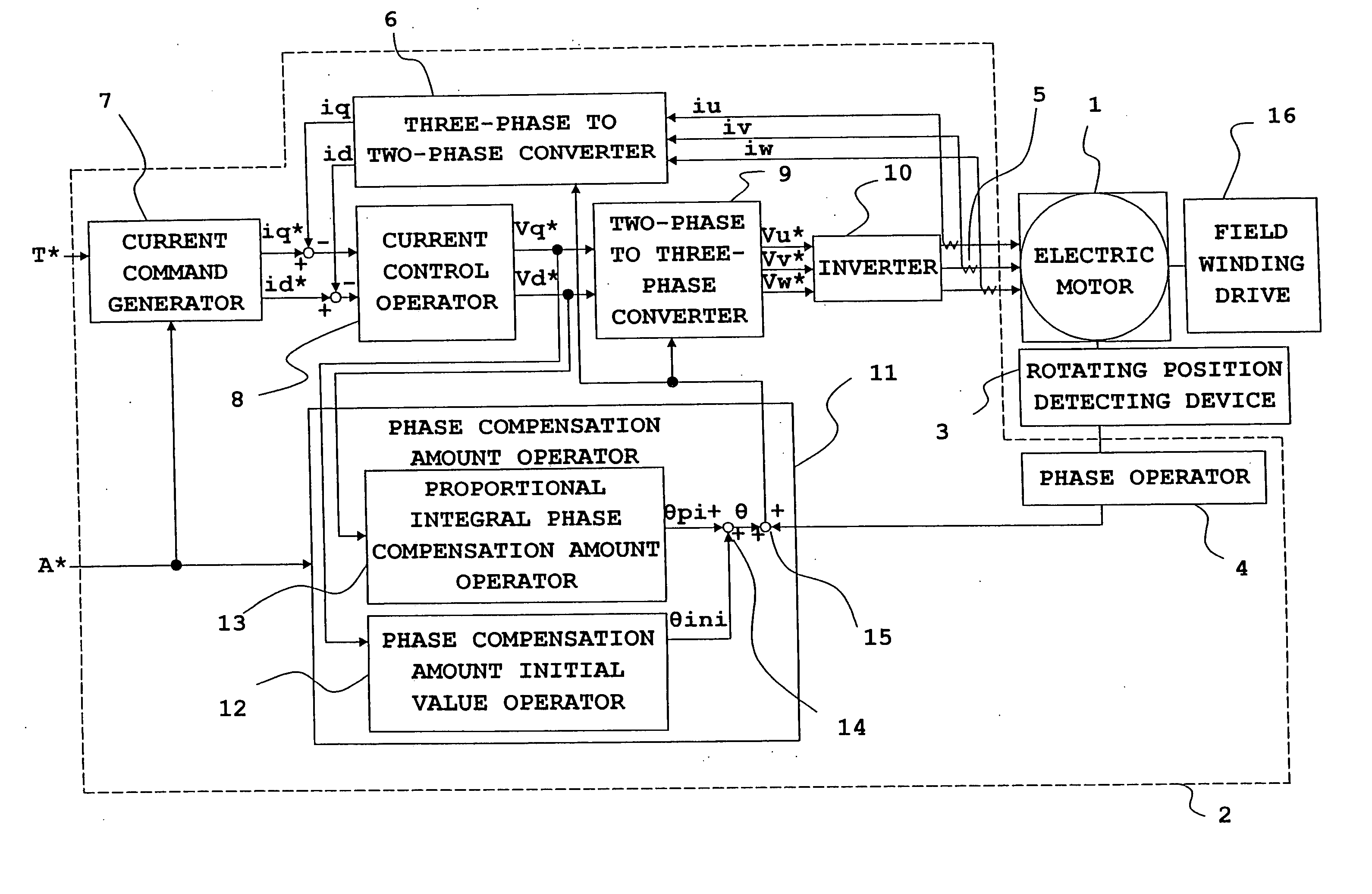
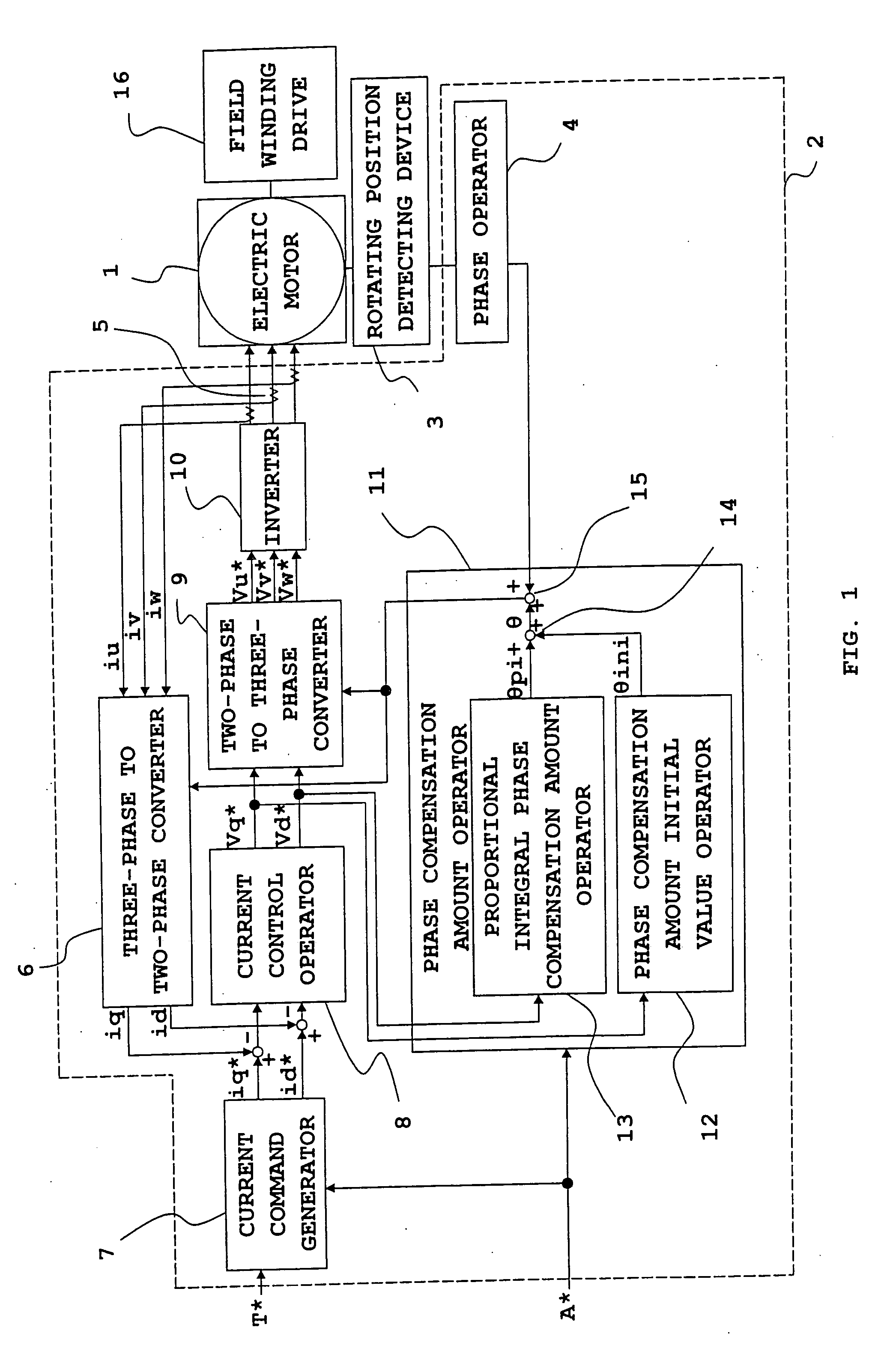
[0056]FIG. 1 is a block diagram of the entire motor control system including a motor control device for explaining an origin offset calculation method according to a first preferred embodiment of the present invention.

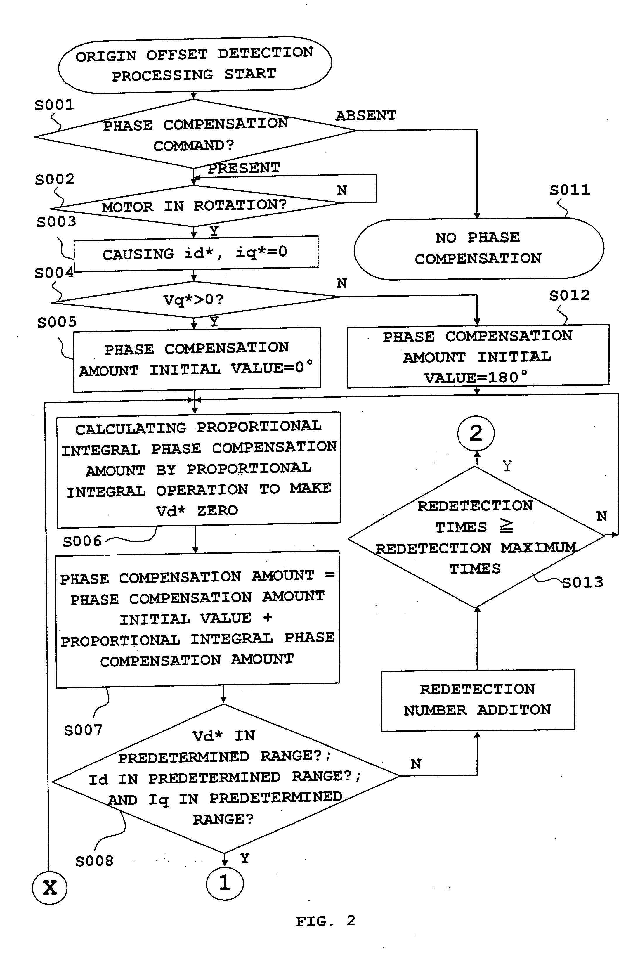
[0057]FIGS. 2 and 3 are flowcharts for explaining the origin offset calculation method of a rotational position-detecting device according to the first embodiment of this invention.

[0058]FIG. 4 is a chart showing the relation between a magnetic flux component voltage command value and a voltage command value of a component orthogonal to this component, and phases for explaining the origin offset calculation method according to the first embodiment of this invention.

[0059] With reference to FIG. 1, to a three-phase synchronous motor 1 (hereinafter referred to as electric motor) including a permanent magnet field or a winding field, a control device 2 to control the electric motor 1 is connected. A rotational position-detecting device 3 that is constructed of a resolv...

embodiment 2

[0093] Although the calculation of an origin offset can be done as described above, it is preferable that the following processes as shown in a flowchart of FIG. 3 may be taken in order to achieve higher accuracy.

[0094]θOffset when Vd* described in the foregoing first embodiment comes to be zero is obtained, and this θoffset is integrated into a buffer, not shown (Step S009). This process is repeated n times (Step S010). Then, n times of results are added up, and a value obtained by the addition is divided by n to obtain an average value (Step S020). This average value is stored (Step S021). Thereafter, a phase compensation command A* is made OFF to return to a normal vector control of an electric motor. At this time, the average θoffset having been obtained is stored in a storage device, not shown, and an origin is compensated using this stored value at the time of normal operation.

[0095] In this case, since an average value of origin offsets θoffset with which Vd* comes to be ze...

embodiment 3

[0096] Furthermore, higher accuracy can be achieved in the following manner. That is, in the case of presence of any detection error in the three-phase current detector, the detection error is outputted even if an actual current value is zero. Accordingly, current detected values id, iq that are obtained by the coordinate transformation with a three-phase to two-phase converter 6 will be values that periodically fluctuate.

[0097] Thus, even if the control is carried out so that the above-mentioned id, iq are compensated to be zero, voltage command values Vd*, Vq* will not be zero, but values that periodically fluctuate. However, the mentioned id, iq will be zero by the calculation of an average value as in the foregoing second embodiment. Further, an advantage is performed such that a phase difference between a rotor reference position and an origin of a rotational position-detecting device can be compensated in the state that detection error of a current detector is canceled.

[0098...


PUM


Abstract

An inverter that executes a d q-axis control of a three-phase synchronous motor needs a rotational position sensor that detects rotational positions of an electric motor for mutual conversion between two-phase and three-phase. An angle error of this rotational position sensor affects accuracy in the d q-axis control, so that it is necessary to make a compensation with accuracy. In the conventional method, however, there is a problem of occurrence of an ignorable error due to influence of noise. An origin offset calculation method according to the invention includes a first process of forcibly making d q-axis current command values zero; a second process of multiplying a magnetic flux component voltage command value at this time by a proportional integral gain; and a third process of storing a rotational position sensor phase error when a magnetic flux component voltage command value becomes zero being a result of the second process.

Description

BACKGROUND OF THE INVENTION [0001] 1. Field of the Invention [0002] The present invention relates to a method of calculating a phase difference (offset) between a rotor reference position of an electric motor and an origin of a rotational position-detecting device resulted from, e.g., the fact that the rotational position-detecting device mounted on the electric motor is located out of position, and to a motor control device using such calculation method. [0003] 2. Description of the Related Art [0004] There is a conventional motor control device that supplies (in both directions) an electric power from a power supply (hereinafter, referred to as inverter) capable of controlling a frequency and voltage, current, and phase to an AC motor (hereinafter, described as a synchronous motor here) thereby controlling a torque or a rotational speed thereof. [0005] In this conventional motor control device, it is necessary to control phases of, e.g., voltage to be supplied based on rotational ...

Claims


Application Information

Patent Timeline
Patent Type & Authority Applications(United States)
IPC IPC(8): H02P7/44H02P1/46H02P6/18H02P6/06H02P6/08H02P6/182H02P6/32H02P21/00H02P21/06H02P21/09H02P21/22H02P27/04
CPCH02P6/142H02P27/04H02P6/16H02P21/00H02P21/0053H02P2205/01H02P25/026H02P2203/03H02P2207/05H02P2209/11H02P21/146H02P6/15H02P21/18H02P21/32H02P25/03
Inventor YASUKAWA, KOUICHINISHIMURA, SHINJI
Owner MITSUBISHI ELECTRIC CORP
Why Eureka
Try Eureka