Switching circuit for current measurement range resistor and current measurement apparatus including switching circuit

Inactive Publication Date: 2006-01-19
AGILENT TECH INC
View PDF7 Cites 0 Cited by
  • Summary
  • Abstract
  • Description
  • Claims
  • Application Information

AI Technical Summary

Benefits of technology

[0012] The circuit in the present invention is configured so as to apply a reference voltage to the input portion of the range resistor that is not used for measurement. Thus, voltages across the range resistor that is not used for measurement can be made equal to each other. The present invention, therefore, provides a circuit in which almost no leakage current flows, even though the insulating resistance of the semiconductor switch used for range switching is not as high as that of a mecha

Problems solved by technology

Although such a semiconductor switch is relatively inexpensive, it has a large amount of leakage current and shows somewhat i

Method used


Image

  • Switching circuit for current measurement range resistor and current measurement apparatus including switching circuit
  • Switching circuit for current measurement range resistor and current measurement apparatus including switching circuit
  • Switching circuit for current measurement range resistor and current measurement apparatus including switching circuit

Examples


first embodiment

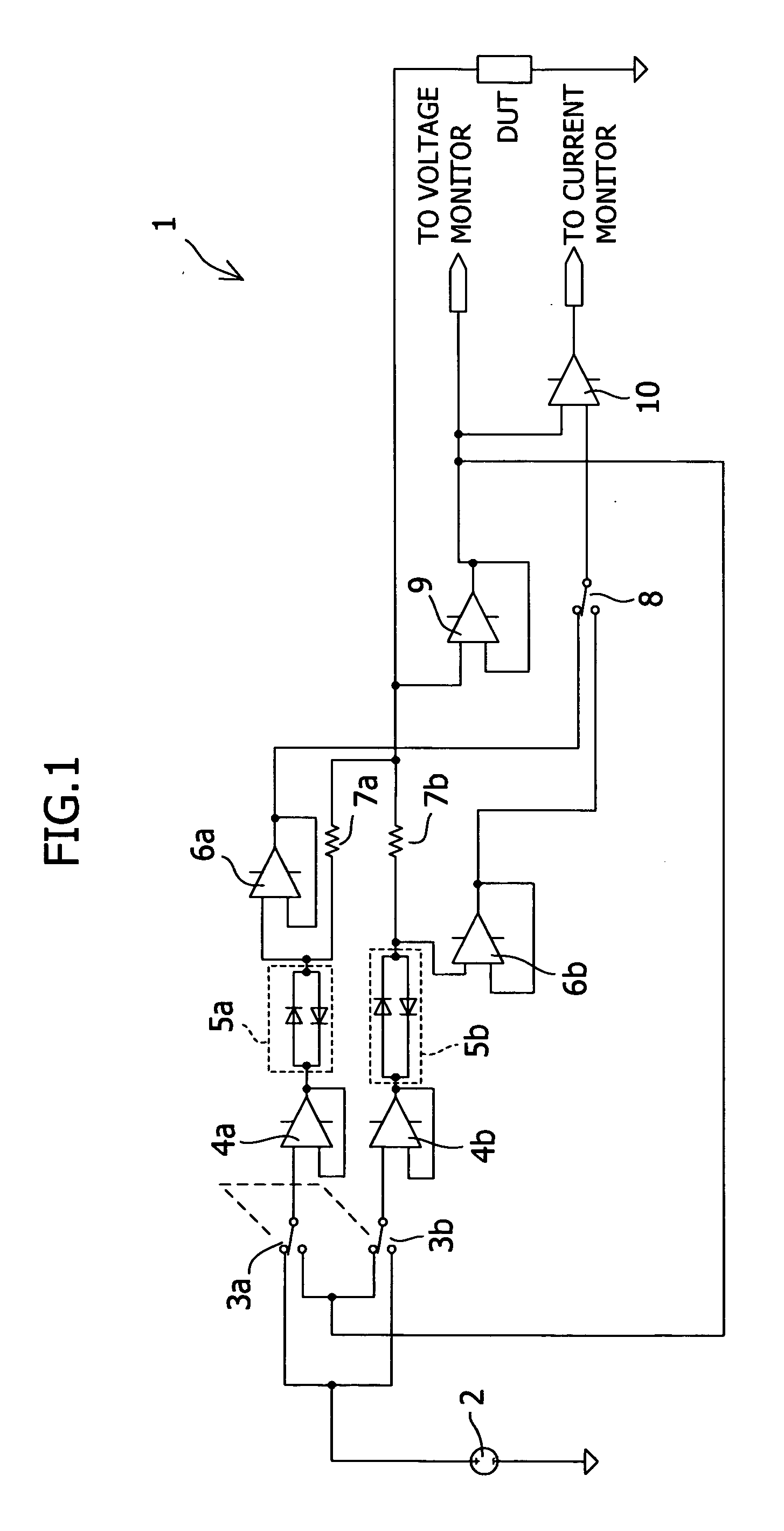
[0017] A circuit according to the present invention will now be described with reference to FIG. 1. In FIG. 1, a switching circuit 1 for range resistors for current measurement includes a voltage source 2 that applies a reference voltage and two first semiconductor switches 3a and 3b that are connected so as to input the reference voltage, applied from the voltage source 2, to respective first input portions. The two first semiconductor switches 3a and 3b have respective output portions, which are connected to two inputs of a second semiconductor switch 8 via buffers 4a and 4b, noise elimination circuits 5a and 5b, and buffers 6a and 6b, respectively. In addition, outputs of the noise elimination circuits 5a and 5b are connected to respective first terminals of the range resistors 7a and 7b for current measurement, which resistors have different resistances. Second terminals of the current-measurement range resistors 7a and 7b, the second terminals not being connected to the noise e...

second embodiment

[0023] Next, the operation of the circuit will be described below with reference to FIG. 1. First, the first semiconductor switches 3a and 3b and the second semiconductor switch 8 perform switching operations so as to select one of the range resistors 7a and 7b, which are current sensing resistors, so that current from the DUT is supplied to the selected range resistors or to select one of the range resistors 7a and 7b so that a voltage at the selected range resistor is measured. Herein, the first semiconductor switches 3a and 3b and the second semiconductor switch 8 are each illustrated as a two-input switch. However, as in the following description for a circuit shown in FIG. 3, the second semiconductor switch 8 is not particularly limited to two-input switches.

[0024] Next, the switching operations of the first semiconductor switches 3a and 3b and the second semiconductor switch 8 shown in FIG. 1 will be described. First, a description is given of a case in which an instruction o...


PUM


Abstract

A switching circuit includes at least two first semiconductor switches, each having a first input portion and a second input portion; range resistors that are provided between output portions of the first semiconductor switches and a device under test and that have different resistances from each other; a second semiconductor switch having an input portion connected to the output portions of the first semiconductor switches; and a differential amplifier having an input portion connected to the output portion of the second semiconductor switch and an input portion connected to ends of the range resistors, the ends being adjacent to the device under test. In accordance with a control signal, a desired one of the first semiconductor switches is connected to the first input portion and the second switch is connected to the output portion of the desired first semiconductor switch.

Description

BACKGROUND OF THE INVENTION [0001] 1. Field of the Invention [0002] The present invention relates to a current measurement circuit used for evaluating / testing characteristics of, for example, an IC (integrated circuit) tester and also to an apparatus including the current measurement circuit. [0003] 2. Description of the Related Art [0004] Examples of known circuits for switching current ranges using relay switches include a circuit disclosed in Japanese Unexamined Patent Application Publication No. 5-119110 (Document 1). The circuit switches a current range resistor 15 using a semiconductor switch, such as a CMOS 32 illustrated in FIG. 1 in this document. Such a semiconductor switch is low in cost compared to mechanical relays (or reed relays) illustrated in FIG. 1 in U.S. Pat. No. 5,994,947 (Document 2), which predates Document 1. [0005] Although such a semiconductor switch is relatively inexpensive, it has a large amount of leakage current and shows somewhat inferior performance ...

Claims


Application Information

Patent Timeline
IPC IPC(8): H03K17/62
CPCG01R15/002G01R1/206
Inventor TANIDA, SHINICHI
Owner AGILENT TECH INC
Why Eureka
Try Eureka