Measurement device

Inactive Publication Date: 2020-05-14
KONICA MINOLTA INC
View PDF0 Cites 0 Cited by
  • Summary
  • Abstract
  • Description
  • Claims
  • Application Information

AI Technical Summary

Benefits of technology

The invention provides a device that can accurately measure thin films on a thick film transparent material.

Problems solved by technology

It is conventionally difficult in the field of regenerative medicine to measure the film thickness of a transparent thin film sample arranged on a Petri dish (thick film transparent medium).
However, in this film thickness measurement method, it is difficult to directly measure the film thickness of a transparent thin film sample arranged on a thick film transparent medium since there is too much optical noise caused by back surface reflection of a commercially available Petri dish or the like.
However, although this reflectance measurement device can be used to calculate the film thickness at one point, it is difficult to reproduce the conditions of focus adjustment, and reflection interference components cannot be perfectly extracted, and thus the film thickness of the transparent thin film sample cannot be measured with high accuracy.
In addition, continuous measurement of the film thickness cannot performed, nor is it possible to perform measurement in a combined manner in water and the air to measure the film thickness of the transparent thin film sample.

Method used


Image

  • Measurement device
  • Measurement device
  • Measurement device

Examples


example 1

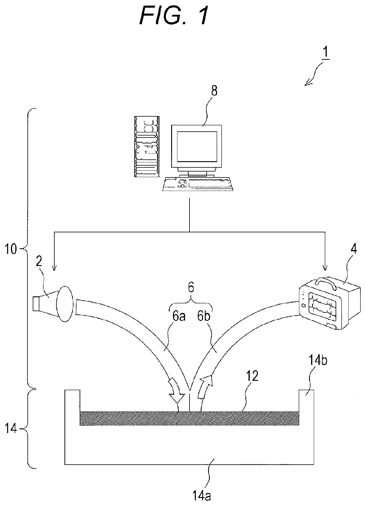
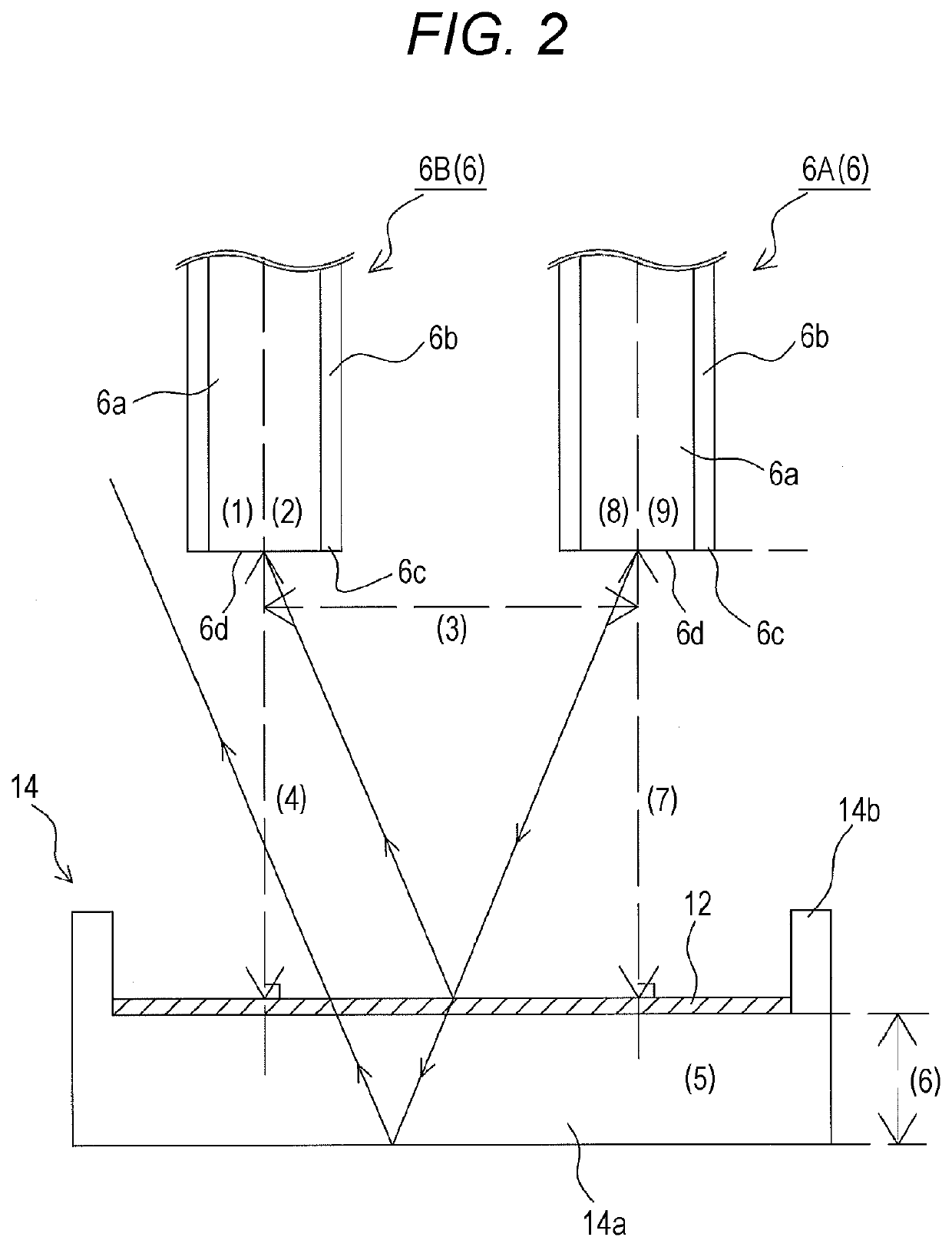
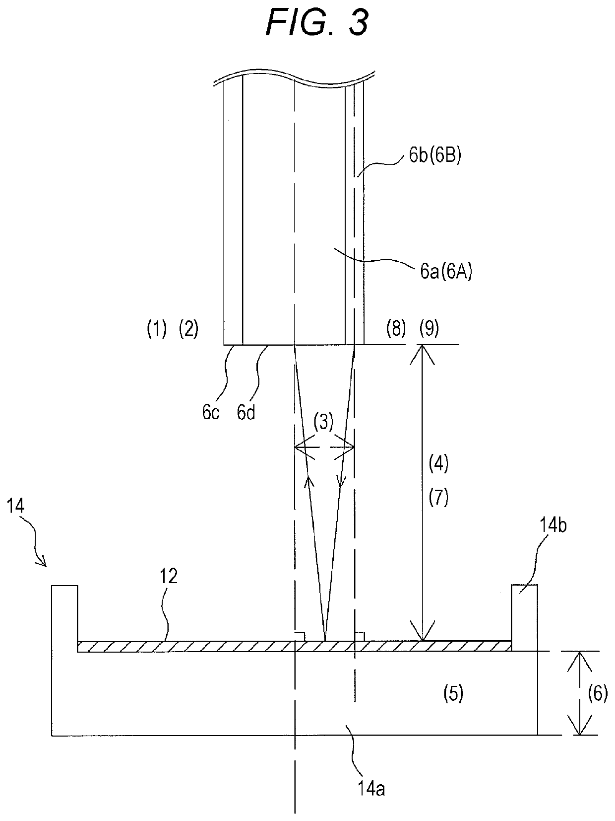
[0150]The MI-Affinity coaxial optical fiber was placed in a dark box, and its height was made adjustable by a Z stage. In addition, a non-transmissive mask made of steel was prepared which has a size that completely closes a φ200 μm core part of the light receiving part 6B and has a 100 μm pinhole opened at the center part thereof. The coaxial optical fiber was improved by attaching the optically black mask so that the core diameter becomes 100 μm and that light projection-light reception interval becomes 0.3 mm. Measurement data was imported from the spectroscope 4 into a personal computer via USB, and spectrum intensity data of the polystyrene Petri dishes applied with the gelatin was normalized and divided by a normalized spectrum intensity of a reference Petri dish not applied with the gelatin to obtain spectral reflectance. The configuration of these measurement devices, theoretical calculation results, and measurement results of the film thickness are shown below.

TABLE 3Device...

example 2

[0153]In the configuration of the measurement device of example 1, only the light projecting optical fiber 6a forming the cladding portion was connected to a white light source (lamp housing MHF-V501, halogen lamp MORITEX LM-50 12V 50 W, both manufactured by MORITEX Corp.) without connecting the light receiving optical fiber 6b that forms the core portion of the attached coaxial optical cable to a light source. Meanwhile, an optical fiber was selected from the following list of optical fibers (manufactured by Edmund Optics) the diameter of which varies, secured at an angle of 0 degrees with respect to the sample surface, and connected to a spectroscope (mini-spectroscope C10535CA-51 manufactured by Hamamatsu Photonics K.K.).

TABLE 6Fiber No.Product CodeApertureNAF15934450 μm0.22F258397100μm0.22F358398200 μm0.22F458399400 μm0.22

[0154]Next, the interval between the light projecting optical fiber 6a and the light receiving optical fiber 6b and the distance between the light receiving op...

example 2-1

[0155]A measurement device of a two-axes measurement system using a 50 μm optical fiber F1 for the light receiving part 6B was used. In both of comparative examples 1 and 2, the incident interference light cause phase inversion, and thus the theoretical formula is not satisfied. As a result, the gelatin thin film on the Petri dish was not measured correctly. On the other hand, it can be seen that the interference light can be measured accurately and that the film thickness is calculated with no problem in the measurement device of the measurements 1 to 4 satisfying the theoretical formulas of the present invention. That is, it became clear that a thin film on the petri dish 14 can be accurately measured by the measurement device of the present invention in which the aperture of the light receiving surface 6d is set to φ50 μm, the distance between the light projecting surface 6c and the light receiving surface 6d is set to be within a range of 0.2 mm and 0.4 mm, and the interval betw...


PUM


Abstract

A measurement device is for measuring a sample arranged on a thick film transparent medium. In the measurement device, a light projecting surface, a light receiving surface, the thick film transparent medium, and a sample are set so as to satisfy the following formula (α) for eliminating noise light reflected from a back surface of the thick film transparent medium: h<(L / n3)·√((2H / D2)·(2H / D2)−n3·n3+1) . . . Formula (α). In formula (α), h denotes a distance from the light receiving surface to the sample, L denotes a half of an interval between the light projecting surface and the light receiving surface, n3 denotes a refractive index of the thick film transparent medium, H denotes a thickness of the thick film transparent medium, and D2 denotes an aperture of the light receiving surface.

Description

TECHNICAL FIELD[0001]The present invention relates to a measurement device for directly measuring the thickness, a change in the thickness, a reaction measurement, a thermal response, water adsorption, etc. of various measurement objects deployed on a thick film transparent medium used in the field of regenerative medicine without any other optical medium interposed.BACKGROUND ART[0002]It is conventionally difficult in the field of regenerative medicine to measure the film thickness of a transparent thin film sample arranged on a Petri dish (thick film transparent medium). In general, as a method of measuring the film thickness of a transparent thin film sample, for example, a film thickness measurement method is known in which the reflection interference spectroscopic measurement of a transparent thin film sample is performed and the film thickness of the transparent thin film sample is measured by conversion into the film thickness. However, in this film thickness measurement meth...

Claims


Application Information

Patent Timeline
IPC IPC(8): G01N21/45G01B11/06G01N21/25G01B11/24
CPCG01N2201/061G01N21/25G01B11/06G01N21/45G01B11/2441G01N21/27G01B11/0625
Inventor NINOMIYA, HIDETAKANAKAMURA, YUKITOKAYA, TAKATOSHI
Owner KONICA MINOLTA INC
Why Eureka
Try Eureka